A No.4 Scraper Plane
Rescued from Oblivion
as a
Cracked Type 11 Stanley/Bailey Smoother
Return
to georgesbasement
 This
little plane came to me courtesy of Sandy Moss as a user Type 11 No.4 smoother.
Alas; the bottom was broken out of the plane. What looked at first like
a small depression in the bottom was instead a big piece of the surrounding
metal ready to fall out. So we renegotiated. Then, it bothered me that
the plane was neither a collector's item nor a user. So I designed a couple
of alternatives: Make it into a scraper plane; or into a low-angle smoother.
I let Sandy decide; this is the result.
This
little plane came to me courtesy of Sandy Moss as a user Type 11 No.4 smoother.
Alas; the bottom was broken out of the plane. What looked at first like
a small depression in the bottom was instead a big piece of the surrounding
metal ready to fall out. So we renegotiated. Then, it bothered me that
the plane was neither a collector's item nor a user. So I designed a couple
of alternatives: Make it into a scraper plane; or into a low-angle smoother.
I let Sandy decide; this is the result.
The machining of the plane is another story that will be added
later. For the time being, here is how it came out.
 The
design loosely follows Stanley's No.112 and No.212 scraper planes, as it
has a center post and tilting frog. However, the pivots of the frog are
much higher up on the cheeks, allowing the addition of a rabbet mouth,
which is found only in the rare No.85 Stanley scraper plane. The cutter
width is 2-3/8 inch, placing it between the No.112 (2-7/8 inch) and No.212
(1-3/8 inch). This design allows the No.4 scraper to work on surfaces that
abut vertical members.
The
design loosely follows Stanley's No.112 and No.212 scraper planes, as it
has a center post and tilting frog. However, the pivots of the frog are
much higher up on the cheeks, allowing the addition of a rabbet mouth,
which is found only in the rare No.85 Stanley scraper plane. The cutter
width is 2-3/8 inch, placing it between the No.112 (2-7/8 inch) and No.212
(1-3/8 inch). This design allows the No.4 scraper to work on surfaces that
abut vertical members.
 A
tilting tote allows the No.4 scraper to be used as a shooting board scraper
or for scraping against vertical members without scraping one's knuckles,
too !
A
tilting tote allows the No.4 scraper to be used as a shooting board scraper
or for scraping against vertical members without scraping one's knuckles,
too !
 The
composite image at left shows the extent of tilt that the tote can reach
each side of center.
The
composite image at left shows the extent of tilt that the tote can reach
each side of center.
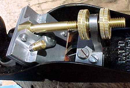
 Here
is an overhead view that shows the frog adjustment mechanism. The center
post is held by the original frog-anchor screws plus two more that I added
for stability; I flattened the top of the frog receiver also, so there
would be a good bearing between the bottom of the center post and the top
of the frog receiver.
Here
is an overhead view that shows the frog adjustment mechanism. The center
post is held by the original frog-anchor screws plus two more that I added
for stability; I flattened the top of the frog receiver also, so there
would be a good bearing between the bottom of the center post and the top
of the frog receiver.
 Here
is the frog taken out of the plane and sitting upside down on the bench.
The cutter is made from a worn-out bimetallic hacksaw blade. No tempering
or other heat treatment was necessary because the back of the bimetallic
blade is already tempered for an optimum combination of strength and toughness.
It is actually too hard to file, but my burnisher can turn its edge with
ease. The high-speed steel teeth of the hacksaw blade were ground off.
Actually, you could make a toothing blade by leaving those teeth on ! The
three screws at the top of the image serve two functions. The two at the
right & left are the lateral adjusters for the blade; and the middle
one clamps the cutter clamping lever's anchor screw so that the lever will
swing in the correct portion of its limited arc of movement.
Here
is the frog taken out of the plane and sitting upside down on the bench.
The cutter is made from a worn-out bimetallic hacksaw blade. No tempering
or other heat treatment was necessary because the back of the bimetallic
blade is already tempered for an optimum combination of strength and toughness.
It is actually too hard to file, but my burnisher can turn its edge with
ease. The high-speed steel teeth of the hacksaw blade were ground off.
Actually, you could make a toothing blade by leaving those teeth on ! The
three screws at the top of the image serve two functions. The two at the
right & left are the lateral adjusters for the blade; and the middle
one clamps the cutter clamping lever's anchor screw so that the lever will
swing in the correct portion of its limited arc of movement.
 Here's
what the frog looks like mostly apart. The heads of the two set screws
in the lever cap at left are seen in the bottom of the previous image.
The lever and its anchor screw are shown together at bottom left, just
above the dedicated screwdriver that's used for fine adjustments on the
plane, and which stows in the hole formerly occupied by the frog-translation
screw that first appeared in Stanley's Type 11 design. At the lower right
is the cutter itself; note the notches which enable it to clear the small
rabbet mouth openings.
Here's
what the frog looks like mostly apart. The heads of the two set screws
in the lever cap at left are seen in the bottom of the previous image.
The lever and its anchor screw are shown together at bottom left, just
above the dedicated screwdriver that's used for fine adjustments on the
plane, and which stows in the hole formerly occupied by the frog-translation
screw that first appeared in Stanley's Type 11 design. At the lower right
is the cutter itself; note the notches which enable it to clear the small
rabbet mouth openings.
 Here's
the tilt mechanism for the frog; the image also shows the cutter clamping
lever. The clamping lever need only be swung a few degrees in order to
clamp the cutter securely, so the small arc of movement is not a handicap.
The depth of cut of the cutter is increased by slackening the front thumbnut
and tightening the rear one; the adjustment is quite easy and can be set
to make gossamer shavings or just dust if desired.
Here's
the tilt mechanism for the frog; the image also shows the cutter clamping
lever. The clamping lever need only be swung a few degrees in order to
clamp the cutter securely, so the small arc of movement is not a handicap.
The depth of cut of the cutter is increased by slackening the front thumbnut
and tightening the rear one; the adjustment is quite easy and can be set
to make gossamer shavings or just dust if desired.
 The
lateral adjustment mechanism for the cutter is based on the toe jack that
a rigger or millwright will recognize in miniature here. The active portions
of the toe jacks are "L" shaped pieces that move in sliding dovetails
in response to threads on their backs. The adjusting screws are captured
by circumferential grooves that are engaged by anchor screws on the back
side of the frog. The adjusting screws bear on 1/16 inch diameter balls
at the bottoms of their blind holes. Turning one of those screws clockwise
lifts that side of the blade to increase its depth of cut; this is easiest
to do if the clamping lever is slightly loosened. Just visible towards
the top left of each of the three images at the right of this composite
is one of the two taper pins on which the frog pivots. Each pin can be
pried out of its socket by gently levering the inner end with the dedicated
screwdriver shown at the lower left.
The
lateral adjustment mechanism for the cutter is based on the toe jack that
a rigger or millwright will recognize in miniature here. The active portions
of the toe jacks are "L" shaped pieces that move in sliding dovetails
in response to threads on their backs. The adjusting screws are captured
by circumferential grooves that are engaged by anchor screws on the back
side of the frog. The adjusting screws bear on 1/16 inch diameter balls
at the bottoms of their blind holes. Turning one of those screws clockwise
lifts that side of the blade to increase its depth of cut; this is easiest
to do if the clamping lever is slightly loosened. Just visible towards
the top left of each of the three images at the right of this composite
is one of the two taper pins on which the frog pivots. Each pin can be
pried out of its socket by gently levering the inner end with the dedicated
screwdriver shown at the lower left.
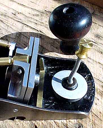 The
front knob is tilted forward (or left or right) in order that one's guiding
hand's thumb doesn't foul the front of the frog. I made the new knob attachment
screw because it's longer than the original, so that one wasn't consumed
in this alteration.
The
front knob is tilted forward (or left or right) in order that one's guiding
hand's thumb doesn't foul the front of the frog. I made the new knob attachment
screw because it's longer than the original, so that one wasn't consumed
in this alteration.
 The
tilting tote is quite a complex mechanism, because the No.4's tote is held
in place by just one screw. There's only one place for the tilt mechanism
to attach if one doesn't want to alter the basic design or drill a hole
through the bottom of the bed.
The
tilting tote is quite a complex mechanism, because the No.4's tote is held
in place by just one screw. There's only one place for the tilt mechanism
to attach if one doesn't want to alter the basic design or drill a hole
through the bottom of the bed.
 There
isn't much clearance between the parts of the tilting mechanism; the tote
is presently 7/8 inch above its original position, but that turns out to
be an advantage because the plane needs more down force than a smoother
to cut consistently, and the higher position of one's grip on the raised
tote (which is a full-size No.4 tote) naturally accomplishes that end.
There
isn't much clearance between the parts of the tilting mechanism; the tote
is presently 7/8 inch above its original position, but that turns out to
be an advantage because the plane needs more down force than a smoother
to cut consistently, and the higher position of one's grip on the raised
tote (which is a full-size No.4 tote) naturally accomplishes that end.
 Here
are the parts of the plane in an "exploded" view. Even here,
there are several major portions still together, such as the frog and the
center post/frog tilt mechanism. Note where I flattened the frog receiver
by removing about 1/8 inch, where I removed most of the brace from behind
the knob (so the chips would not accumulate between the frog and that brace),
and where I opened the mouth to 0.7 inch from the original 0.2 inch or
so. That last modification was what was necessitated by the cracked floor
of the Bailey's frog receiver. The metal was only 0.025 inch thick where
it cracked. One reason it cracked was that the two screws that held the
frog only engaged a couple of threads each in the bed - not Stanley's best
quality effort, to be sure.
Here
are the parts of the plane in an "exploded" view. Even here,
there are several major portions still together, such as the frog and the
center post/frog tilt mechanism. Note where I flattened the frog receiver
by removing about 1/8 inch, where I removed most of the brace from behind
the knob (so the chips would not accumulate between the frog and that brace),
and where I opened the mouth to 0.7 inch from the original 0.2 inch or
so. That last modification was what was necessitated by the cracked floor
of the Bailey's frog receiver. The metal was only 0.025 inch thick where
it cracked. One reason it cracked was that the two screws that held the
frog only engaged a couple of threads each in the bed - not Stanley's best
quality effort, to be sure.
 The
plane cuts gossamer chips; here the wood is Andaman Padauk (Pterocarpus
dalbergiodes) the same stuff used by Sargent for their "East Indian
Mahogany" totes & knobs. I bought two boards in a New Jersey lumberyard,
thinking it was Brazilian rosewood. Darn.
The
plane cuts gossamer chips; here the wood is Andaman Padauk (Pterocarpus
dalbergiodes) the same stuff used by Sargent for their "East Indian
Mahogany" totes & knobs. I bought two boards in a New Jersey lumberyard,
thinking it was Brazilian rosewood. Darn.
Anyway, the plane works fine now as a scraper instead of a smoother.
Go back to
top of page