|
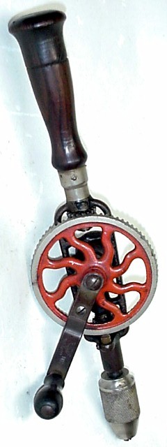
This drill looks nonsensical because it has the frame
used with the "little
railroad car wheel" but also
has two
pinions.
One or the other feature has to be
superfluous. This drill is apparently a prototype used to try out
a way of making the transition from the LRRCW models to the widespread
two-pinion models.
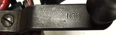
The present drill therefore represents an example of on-the-fly development of a new product at the Millers Falls Company - they made this drill in order to try out a new feature of the No.2 drill., using old stock parts. Clearly they never intended to retain the boss that once held the LRRCW assembly on the castings for their new-style two-pinion drills ! Close examination reveals that the frame is that of a Type D drill (the main gear runs on a steel shaft inserted into the frame rather than on an integral shaft). |
|||
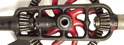 |
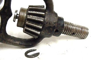
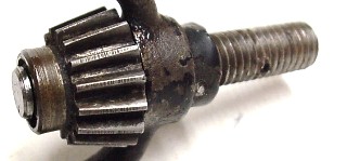
 On
the far left one can barely see the C-clip that retains the second
pinion
on the main-handle stud extension. Also, the steel insert can be
seen
protruding from the central boss of the frame. This
was a new feature of Type
Post-E and later drills. The inset at left shows the
spot-faced surface against which the
second pinion bears. This
machining was done similarly to the finishing of the frame for the main
pinion. On
the far left one can barely see the C-clip that retains the second
pinion
on the main-handle stud extension. Also, the steel insert can be
seen
protruding from the central boss of the frame. This
was a new feature of Type
Post-E and later drills. The inset at left shows the
spot-faced surface against which the
second pinion bears. This
machining was done similarly to the finishing of the frame for the main
pinion. |
|
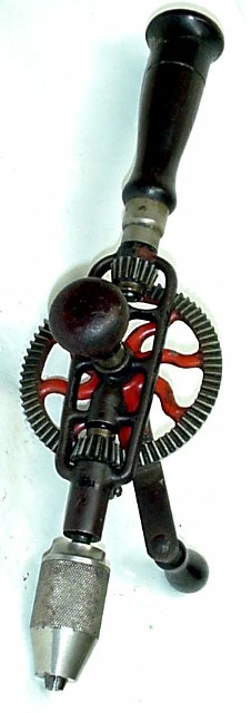
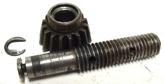
The image at far
left shows the pinion components taken out of the drill, which was easy
to do, as the two cross-pins were not peened in place, nor were they
severely
distorted by heavy use. The image at right shows the first step in the sequence of assembly of the second pinion. The stud is first threaded into the frame far enough to allow the C-clip to be inserted, and then the stud is backed out to a position where the pinion has a good running clearance. Lastly, it is pinned to the frame, which sets the running clearances "forever." The two images at bottom show how well the C-clip is hidden inside the recess machined into the smaller end of the second pinion. In the right-hand image the stud is now pinned. The "production" Type D drills' cross-bars were made with a boss in the center to acommodate an extended pinion shaft, which made the main handle much steadier. This drill's main handle wobbles along with the pinion, because it isn't possible to make the stud a tight fit in the hole tapped into the frame and still assemble the pinion onto the main-handle stud. |
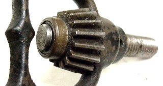
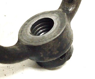
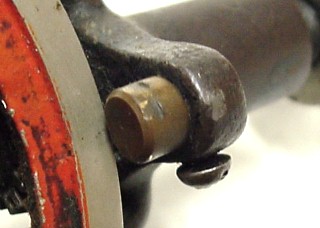 In the
end, this particular drill was quite unsuccessful because of the wobbly
handle and because the meshing between the main gear and the drive
pinion is quite sloppy. That was what the original LRRCW
mechanism was so good for adjusting ! There is also a chance that
the main gear has been replaced, as the wear patterns on the drive
pinion's teeth do not align with the teeth of the main gear. As
seen at left, the worn spots on the brass stud filling the hole where
the LRRCW used to fit also fail to align with the rim of the main
gear. On top of all that negative evidence, the main gear fits
too tightly on its shaft, and so comfortable rotation of the crank is
difficult.
In the
end, this particular drill was quite unsuccessful because of the wobbly
handle and because the meshing between the main gear and the drive
pinion is quite sloppy. That was what the original LRRCW
mechanism was so good for adjusting ! There is also a chance that
the main gear has been replaced, as the wear patterns on the drive
pinion's teeth do not align with the teeth of the main gear. As
seen at left, the worn spots on the brass stud filling the hole where
the LRRCW used to fit also fail to align with the rim of the main
gear. On top of all that negative evidence, the main gear fits
too tightly on its shaft, and so comfortable rotation of the crank is
difficult.