Fixin' the Mysterious & Puzzling 2101A's
Ratchet Mehanism
by George Langford
Revised & Expanded February 22, 2007; Another Fix Added April 4, 2016
Return
to georgesbasement
| Several Galoots have been stymied by their Bell Systems B, North Bros. Yankee 2100, 2101, or 2101A, or Stanley 2101 braces when the ratchet mechanism has either become damaged or gummed up. As everything's inside, one can't easily squirt a liitle oil in there; nor can one judiciously pry ... |
 |
Here's
my puzzle. This brace had essentially never been used when I acquired it
at Shupps Grove a number of years ago. One reason will later become apparent.
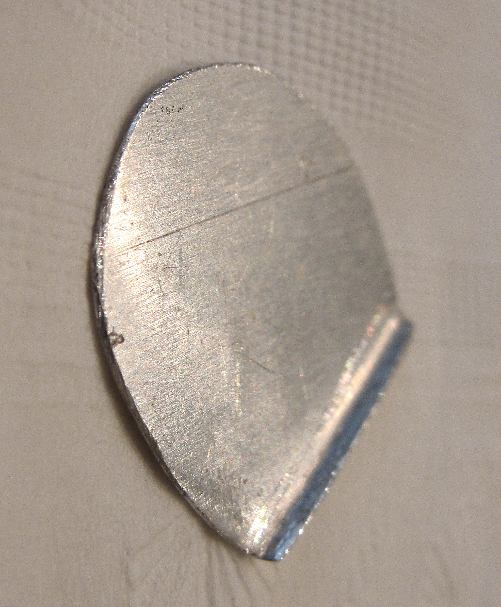
However, the plunger that changes the direction of ratcheting or locks
the mechanism was stiff to operate, and the ratchet sometimes refused to
operate at all. Either the spindle would spin freely ... or not at all. That's my submarine-hull-steel anvil at right. Faced with a disk about 2-1/2 feet across from which to cut enough material to make a few impact specimens that would fit in your coat pocket, I pursuaded the welder hired for that purpose (with a little extra in cash) to cut along a chalkline around the remains of the disk before chucking the rest. I then sawed and ground the horn, planed the top & bottom with my Pratt & Whitney metal planer, and heated the whole thing as one would do a chisel - quench the horn & table in water and then let the residual heat temper the hard parts before quenching the rest, which by then will have lost their ability to harden. Worked like a charm; that was over twenty years ago. |
 |
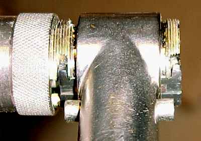
The
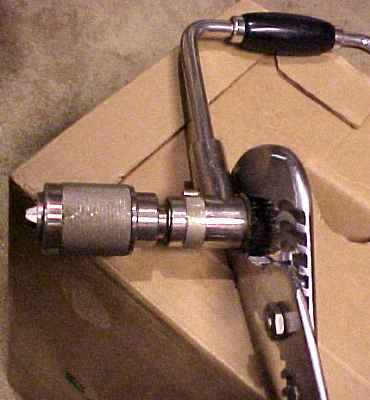
first step in disassembly of the ratchet mechanism is to loosen the
rear
nut that caps the mechanism. Here I'm using a pair of large
Channellock-style
pliers. There is a piece of leather from an old belt cushioning
the nut's
delicate knurling. It should not take much force to break the
nut's grip, and there are no forces in normal operation that tend to
loosen it. For some idiotic reason, many of these braces have
received severe blows against this cap, probably in vain efforts to
start the screw tip of a bit ... |
 |
With
the nut successfully unscrewed, the reason for the brace's reluctance
to
ratchet became apparent. This green goo was gluing it all
together. Usually,
it's only the Bell System braces that are afflicted this way. [I've
recently found a non-Bell Systems brace with the Green Goo, so it must
actually have been the Stanley wizards after all - GL]. Theory
had
it that Ma Bell didn't trust her employees to apply the few drops of
oil
every decade that it takes to keep the brace functioning. The
grease packed
into this brace's ratchet box seems to have reacted with the nickel
plating
to produce the green color of nickel oxide. Just a theory. |
 |
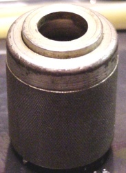
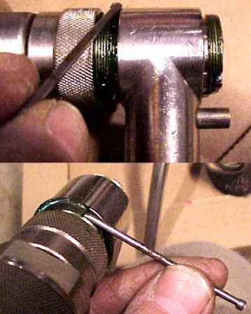
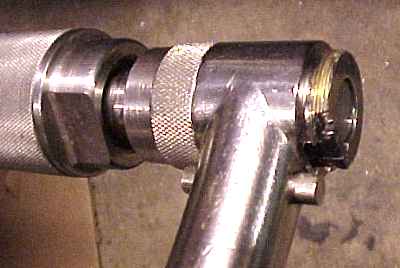
 The
second nut unscrews just like the first one; they've both got right-handed
threads, by the way. The
second nut unscrews just like the first one; they've both got right-handed
threads, by the way.An alternate method of protecting the chuck shell and the nut's knurling is shown at right. That's a piece of plastic pipe (nominally one inch size - more like an inch and a quarter) that I cut in half. That pair of wood blocks with the Vee's cut in them works wonders for gripping the chuck without distorting the shell. |
 |
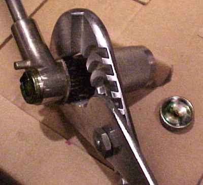
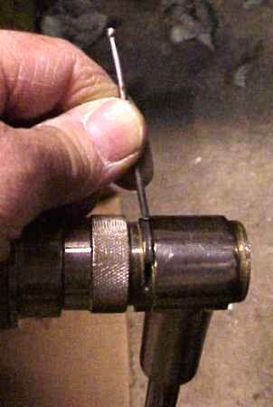
Once the second nut's been loosened and moved as far as it will go out of the way, you can then drive out the half-moon-shaped key that keeps the spindle in place. I used a 2-1/2 inch long finishing nail whose point I ground flat. The nail's not hard enough to damage the key. The key is a very snug but not really tight fit, so it slides right out with a few taps on the nail. |
 |
With
the spindle out, the green goo is really evident. And sticky. Much later than this example, I recently did this operation on a half-dozen 2101A braces, and I found all of them but one (which someone else had already cleaned) full of Green Goo in various stages, even rock-candy hard. |
 |
With
the spindle out of the way, the next step is to remove the two
pawls. In
this image the rear pawl is already out, and the front one has been
tilted
part way out. These are both fingertip operations; the rear pawl
just slides
out, but the front one has to be tilted to get it out of its closed
pocket. It helps a lot to move the direction selector pushbutton
away from the outboard end of the brace, as though to ratchet backwards. |
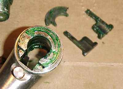 |
Here
the two (identical) pawls are out, and one can see one end of the delicate
spring peeking out of the ratchet box. Be careful this spring or its fragments
(sigh ...) aren't lost. The pawls may show some wear. If there's a bur along the thinner part, it's OK to file that bur flush with the edge. It takes only a few strokes with a file, and it keeps the bur from catching the ridges on the spindle on the backwards stroke, which can render the ratchet useless. An easy fix. |
 |
This is that very delicate phosphor bronze spring, which comes staked to a tiny little pin which fits an equally tiny hole in the selector plunger. This is why you don't hammer on that plunger when it gets stuck ... You might find it necessary to straighten your spring to approximately this contour. On another of my braces, I had to use a hammer to flatten it against the anvil seen in the picture at the start of this page and to straighten a tendency to curve in the wrong plane. In the worst case you might have to make a replacement; Galoot Randy Moore wrote to me recently with such a request for advice, so I tried to describe in words how to go about making the replacement without using fancy tools. |
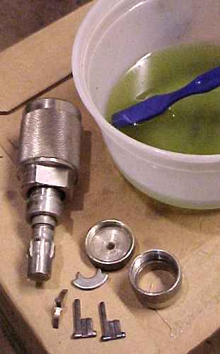 |
OK
- twenty-five minutes later, here are the nice clean parts. Fortunately,
I had no rust to remove. Just the caked-on Green Goo, which can be seen
coloring the solvent. I now recommend just scraping the Green Goo out of the important places and leaving an identifiable residue where it won't do any harm, so future historians can still learn from the brace after you've used it for another lifetime. |
 |
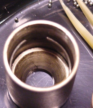
Here's what the ratchet box looks like inside. They're all non-magnetic and apparently made as brass castings. |
 |
And
now the spring's pin is back in the cross-drilled hole in the selector
plunger. It helps to have a pair of tweezers to do this without too much
fumbling; the sharp corners of the flat spring catch on just about every
corner inside the ratchet box ... |
 |
Although
I made this picture before cleaning the pawls, I need to show you here
that the pawls have two different grooves - one on each side. The square-bottomed
groove is the one into which the flat spring fits; and the round-bottomed
groove is clearance for the spindle. As long as you put the flat-bottomed
groove facing outwards, towards the flat spring, there's no wrong way to
assemble the two identical pawls. Trust me. |
 |
Put
the front pawl in first. That's the one that's closer to the chuck. You'll
need to play with the selector plunger to get the pawl to stay put with
the flat spring seated in the flat groove in the pawl, and the pawl has
to be tilted to go into its closed pocket, seen below. |
 |
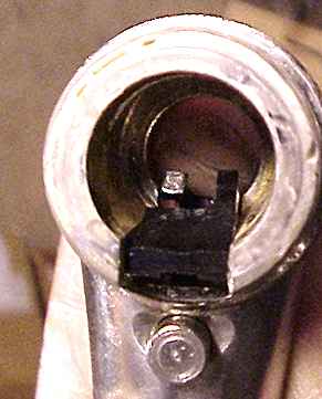
Here's
a rear view of the front pawl in place, with the other end of the flat
spring waving in the breeze at the center of the image. The pawl will stay
put like this only when the selector plunger is pushed in as shown. |
 |
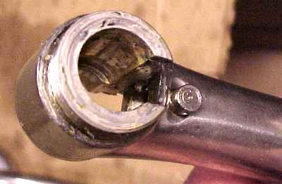
Here's
what the head looks like, all nice and clean. The rear pawl
slides right
into the pocket on the left, but the front pawl has to be wormed into
the
closed pocket at the right. Beware - when later on you're sliding
the spindle back in, it's easy to push the rear pawl out of place, and
then the spring ends up on the wrong side of the pawl. I find
that putting the rear cap back on temporarily helps guard against this
error. |
 |
Now
I'm holding the rear pawl in place with my fingertip as I prepare to
slide
the spindle back into the head of the brace. The front pawl is already
in
its pocket here. Be sure that both ends of the flat spring are
underneath
their respective pawls and not poking up between the ends of the
pawls.
The front pawl has sprung upwards a little, and I had to push it back
down
as I placed the spindle inside the ratchet box. My fingertip also
holds the front pawl (at the rear of this picture) in place so it
doesn't get pushed out. |
 |
Now
the spindle is back in, and the two ends of the flat spring can be seen
correctly seated in the flat-bottomed grooves in the two pawls. At least,
_I_ could see that, even though the camera didn't ... Note that the rear
pawl at right has an open-ended pocket, but the front pawl's seat is closed.
That's why the front one has to be tilted to get it in there. |
 |
We're
gettin' near the end now. The key has been pushed part way into the slot
at the front of the ratchet box. Be sure that the spindle is all the way
in here; you must screw the front nut as far on as it will go without actually
getting in the way of the key in order to be sure that the spindle is all
the way in, or the key will interfere with the groove in the spindle and
possibly damage it when you tap it into the keyway. |
 |
Here I'm getting set to tap the key the rest of the way in. |
 |
Now
the key is securely locking the spindle into the ratchet box. If
your key
has evidence of wear, I used to advise to turn it the opposite way that
it came out in
order to equalize that wear on both sides of the key. However,
then the spindle may not turn freely - that's been my experience - look
at the key as you remove it and then replace it exactly as it came out. |
 |
Now that the front nut is back in place, place some medium weight, non-detergent lubricating oil inside the ratchet mechanism. I used several drops, and none has yet to leak out. |
 |
Now you can tighten both nuts. Done. |
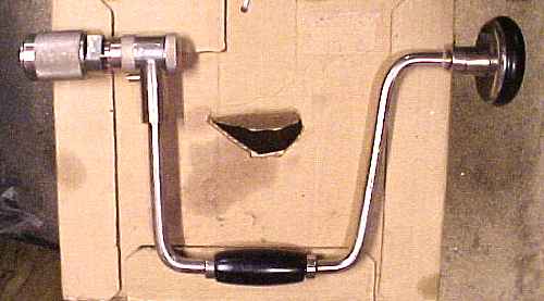 |
This
is the 14-inch size. |
 |
Great
... except for that one sticky problem. It's the crank handle, which is
too tight, so it will only turn if I grip it tightly while operating the
brace, even with oil. If one of you has seen a broken handle and can describe
to me whether it's got a pocket inside or just has a straight-through hole,
I'd appreciate hearing from you. Wunna these days I'll figure out a way
of loosening that handle, I hope. A few days ago I applied these techniques to six braces (with re-runs on two of them) in about three hours. |
 |
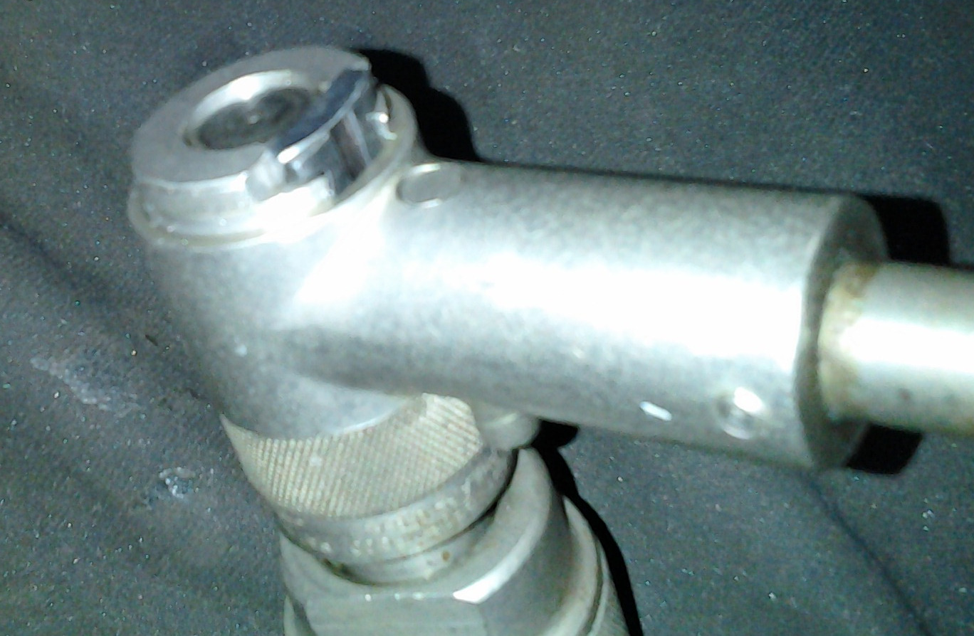
Here's what's going
on inside at least one (destroyed) Yankee brace's wrist handle.
The collar screws onto threads that allow you to adjust the end play of
the wrist handle. Note that, contrarily to the original patent
for this brace, there is no metal sleeve inside the wrist handle. |


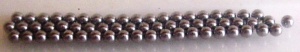


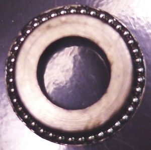
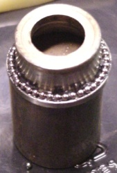
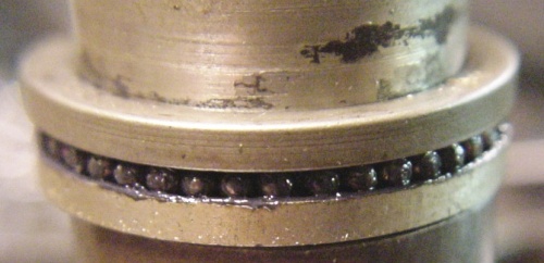 Here are the forty (? - you count 'em) 3/32nd inch balls in place around the race of the chuck.