A Research Study
by George Langford, Sc.D.
Return to Main Page
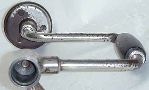
Stanley No.810-10IN. SW (Sweetheart) brace
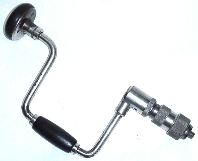 |
This is the
finest brace Stanley ever made. It has a
sixteen-step ratchet mechanism that exhibits virtually no drag in the
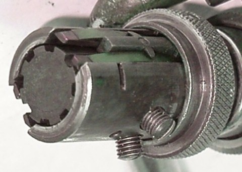
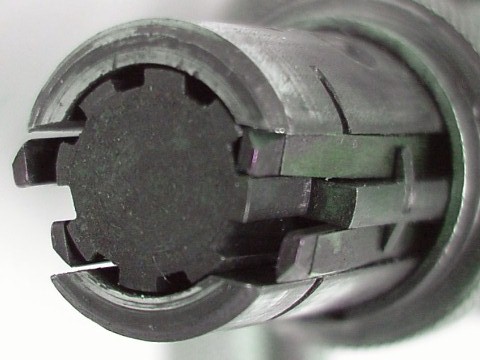
reverse direction. It also has a ball-bearing chuck that will
hold all bit shapes, including square shank augers, round shanks, and
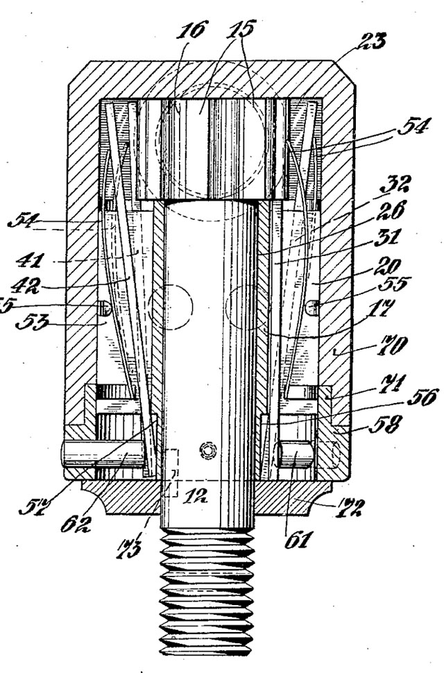
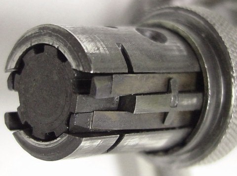
No.1 Morse taper. The ratchet mechanism is bewildering as seen in the patent drawings and only slightly less so as seen here.
|
||||
 |
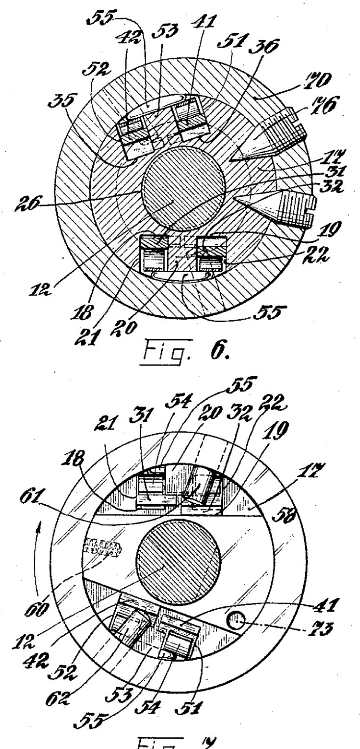
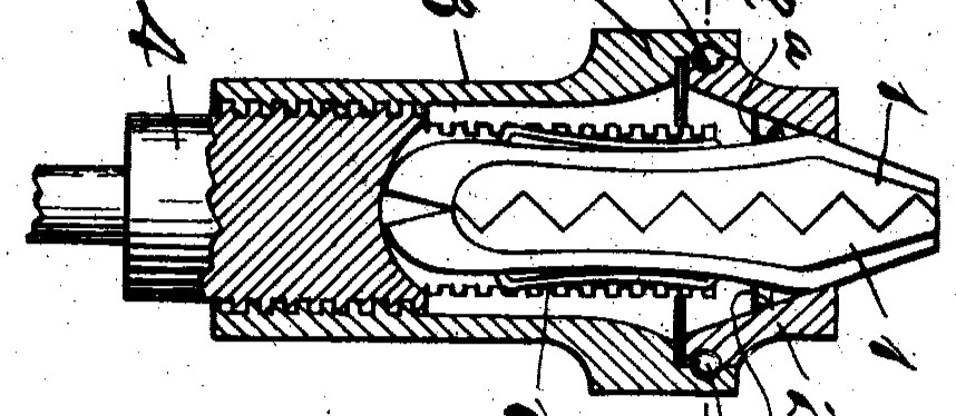
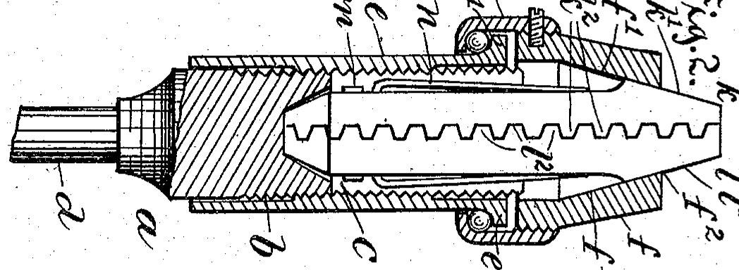
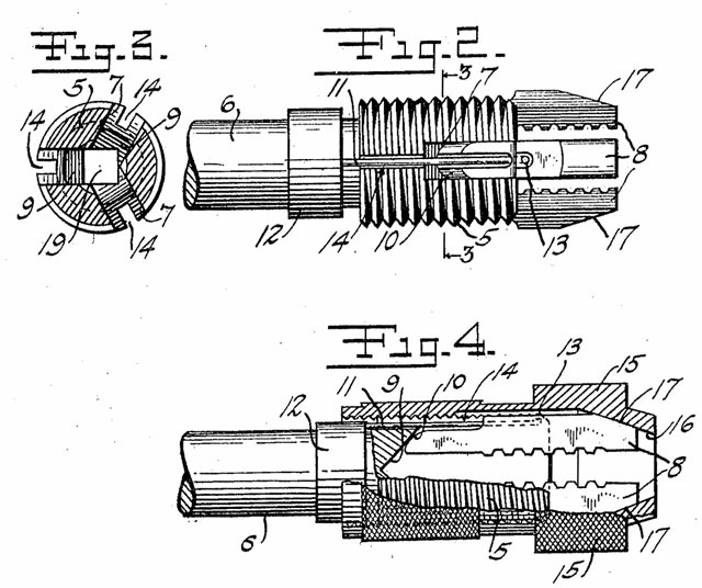 Although the drawing for
H.E.Parker's US
Patent No. 1,270,754 shows
three jaws, the sliding sleeve (#12 in the drawing) that anchors the
springs will acommodate any number of jaws. Although the drawing for
H.E.Parker's US
Patent No. 1,270,754 shows
three jaws, the sliding sleeve (#12 in the drawing) that anchors the
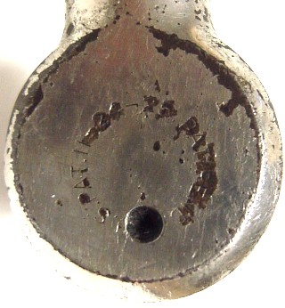
springs will acommodate any number of jaws.Replacement of a spring would require complete disassembly of the spindle and ratchet mechanism in order to remove the sleeve from the spindle. Don't try this at home ... The sleeve is stamped with the 6-25-18 patent date. |
 |
 |
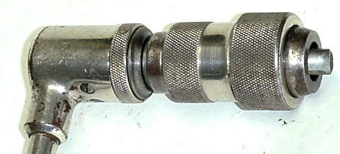
The ball bearings in the chuck are said to follow
Bartholomew's US
Patent No. 927,478 (far left) but to me they more
closely
resemble H.V. Smith's long-expired US
Patent No. 542,448
(center). The
brace's outer shell screws onto the body, and then is affixed by a set
screw (not seen above) at the rear of the outer shell. In
Bartholomew's patent, the balls are loaded into the space between the
elements through a hole drilled in the outer shell, the hole later
being closed with a headless screw. |