Millers Falls No.2 drills have
often lost their roller assemblies (LRRCW's in my Millers Falls No.2
Type Study) and so I'm occasionally asked
for replacements. As I have no leftover LRRCW's or their
associated parts, I've had to reply negatively. I decided to make
some replacement assemblies, but I also decided not to make
counterfeits.
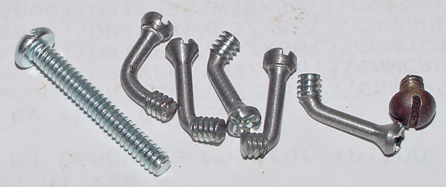
Here's my solution: I am making redesigned LRRCW assemblies that do not
require a screwdriver for adjustment. I'm making the rollers
themselves from scrap bronze (i.e., broken tensile test
specimens) which is a nice way of recycling
as well as a way of making use of the work hardened condition of the
material, which cannot be heat treated to increase its wear
resistance. Rather than just making the offset cams with a
screwdriver slot, I'm adding a projection to facilitate grasping the
cam in order to adjust it. The normally standard No. 6-32 screw
that clamps the assembly will now have a crank shape so that it can be
tightened with one's fingers. Rather than trying to develop a
heat-treating process for the cams, which are lightly loaded, I'm using
drill rod as the raw material, as the carbides in the annealed
microstructure will provide some wear resistance. All you need do
is remember to oil the assembly every few years !
|
|
|
|
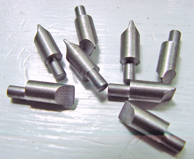
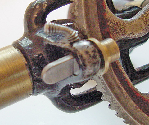
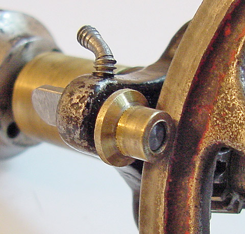
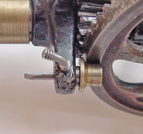
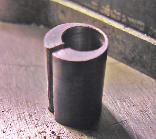
These three views show the LRRCW assembly.
|
Normal LRRCW shape, but in bronze.
|
Properly adjusted LRRCW assembly.
|
Another drill had its cam hole placed wrong.
|
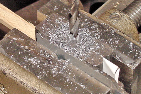
The eccentric cam requires some precise machining. I made a
holding tool for the blanks by offsetting a piece of 3/8 inch round
barstock in the four-jaw chuck so that its axis was 0.048 inch off the
center of rotation of the lathe spindle and then drilling and reaming a
0.250 inch through hole. The 0.152 inch diameter part of the
eccentric cam has to be tangent to one side of the 0.250 inch body of
the cam to maximize the range of adjustment of the LRRCW and yet still
allow putting together the main gear and LRRCW assembly. I got it
right on the first try !
|
|
|
|
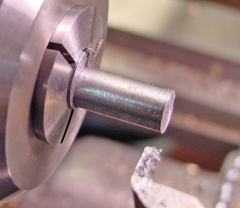
Saw cut was made with a piece of bar inside.
|
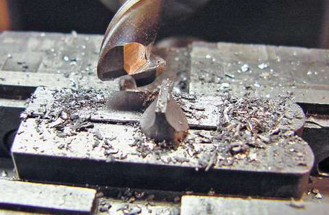
Rod faced off & ready to machine eccentric.
|
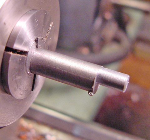
Another eccentric cam ready to be cut off.
|
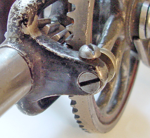
LRRCW reshaped to allow LRRCW adjusting.
|
One drill had its 0.250 inch eccentric cam hole drilled in the wrong
place, so I had to enlarge the replacement LRRCW so that it could be
adjusted properly; this drill probably was a factory second and did not
have a LRRCW when I obtained it. The far-right-hand images in the
two rows above show the problem and its solution. More to come:
making the LRRCW itself.
|
|
|
|
After
the
above debacle over the center distance and diameter of the LRRCW, I made
some measurements of the drills in my Millers Falls No.2 Type
Study. I found that the center distance between the main shaft and
the hole for the eccentric cam was usually about 0.81 inch, with all
the measurements falling between 0.75 and 0.83 inch, but the LRRCW
varied in diameter significantly, as shown at left.
|
Types K through H have LRRCW's that usually measure around 0.31 inch
(5/16th inch), but the later Types G through D have smaller LRRCW's,
about 0.28 inch (9/32nd inch). Oddballs include a couple of 1/4
inch LRRCW's in the earliest Type K drills, which may have been either
worn or replaced. There is one large LRRCW in a Group III,
Type G drill that was probably commandeered from an earlier type.
Nearly all of these drills were made while the company was still located
in Millers Falls, Massachusetts. The histograms were made with PSI-Plot.
|
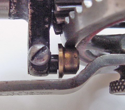
The No.2 Millers Falls drill at left with my LRRCW-GB installed.
This drill came to me with just a 1/4 inch slug of steel in the hole
that was meant to hold the LRRCW cam. It did serve a portion of
the original purpose, as the slug had a small flat spot worn into it
from rubbbing against the larger gear wheel.
I'm all set to make a bunch of bronze LRRCW's. However, I'm
slowing down a little and doing them one at a time for the half dozen or
so No.2 drills that I have that are missing the LRRCW assembly or just
the LRRCW itself. The statistics are in favor of making the
LRRCW's all one size (see the analysis I did above) but I'm still going
to work my way through this group and see how they turn out.
I'll make replacement LRRCW-GB assemblies for your drills if you wish -
Price $20, plus shipping in a First Class padded envelope.
These LRRCW-GB assemblies adjust easily to keep the gears meshing on
their pitch lines, and without any need to resort to tools - the clamp
lever holds the cam securely and won't unscrew and get lost unless you
move the main gear wheel out of the way. After unclamping the cam,
the tab lets you adjust the position of the bronze LRRCW with your
fingers, with visual feedback to simplify the task.
Orders to:
|
|