11. Making Main Gear Screws for No.2 Drills.
These screws are rarely found missing or broken on either of the later
models of Millers Falls No.2 drills, whether they be the LRRCW variety
(where the screw has virtually no loading) or even the two-pinion
drills, where the main gear screw handles the forces between both the
main pinion and the idler pinion. That said, I have gotten an
inquiry,
and so I made a half-dozen screws anyway. Not a simple task, because the
screws have to fit flush against the integral shaft upon which the main
gear rotates, and the tapped hole wasn't counterbored by Millers Falls,
necessitating relieving the chased threads, which is what Millers Falls
did, and in turn making a setup to slot the head, which had to be
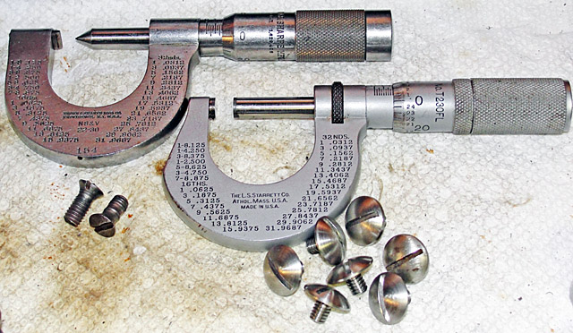
solidly supported because of its fragile waist. These screws have a
No.10 diameter but 28 threads per inch instead of the standard 32
threads per inch.
|
|
The
material that I chose is non-magnetic Type 303 free-machining steel,
which looks a lot like chrome-plated steel, but which doesn't
rust. It has a nasty reputation for work-hardening
dramatically when machined with dull tools, because its austenitic
face-centered cubic structure isn't stable and transforms to hard
body-centered martensite upon severe deformation. It's OK if the
martensite forms in the chips, but not OK when the martensite forms in
the machined surface.
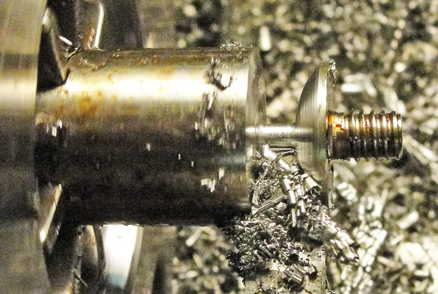
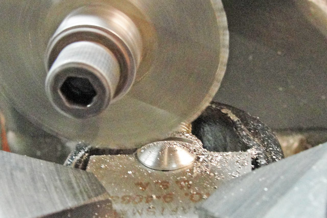
Therefore, I was a little apprehensive about making the oval profile of
the heads of these screws by using a form tool instead of making a
spherical-turning attachment for the lathe. As seen at left, there is
nearly a half inch of active cutting edge at work while the form tool is
doing its job. I found that I had to run the lathe at its slowest
back-gear speed and apply a lot of force to the cross-feed screw of the
carriage, but there were no complaints. I did have to adjust the
bit holder to minimize its overhang in order to keep it from chattering.
I only had to sharpen the tip
of the
cutter once during the making of the six screws that I made, and I was
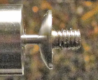
able to preserve its outline by grinding only the top of the cutter. As
seen in the inset, the form tool could make nearly the entire top of the
head of the screw. After this step I sawed off the screw at the
neck and faced it off while held in a 3/16th inch collet. I had
forgotten to relieve the threads of this one screw, which I did later
with a rattail file. All the rest were relieved by undercutting their
heads with a small radius tool before parting off with the form tool.
|
|
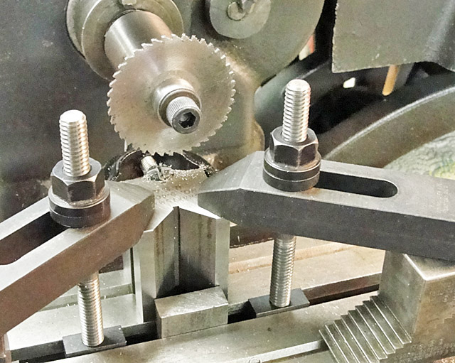
The
slotting saw that I used is 0.052 inch thick but has a 9/16th inch
hole, so I had to make the arbor seen at left. The arbor has three main
components: The main body, which is 0.499 inch to slide into the 0.500
inch hole of the end-mill
holder that fits the No.2 Morse taper hole in the spindle of the Atlas
milling machine; a cup to fit over the 0.513 inch extension of the main
body so I didn't have to thread outside of the extension; and a 5/16-24
Allen head cap screw to clamp the slotting saw onto the arbor. I added a
small steel washer as an expendable wear plate.
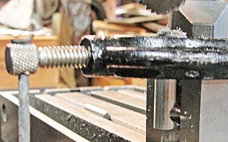
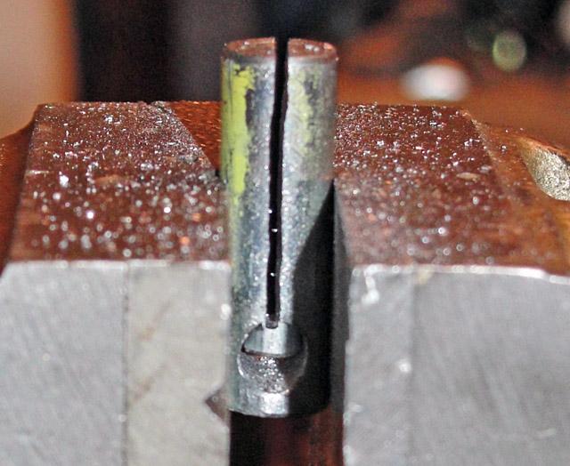
The screw being slotted is a dummy that I used to demonstrate the setup
for this early picture; it is held in a slotted collet that is clamped
into the smaller Vee
on the back side of the Vee block, which is clamped vertically in
alignment with the 0.375 inch thick steel block standing inside the Tee
slot of the main table of the milling machine. This block helps to keep
the Vee block from rotating.
|
|
The two insets above show how the
collet functions and how it was made from a 3/8 inch steel round by
drilling it axially with a 3/16th inch hole, cross drilling, filling the
hole with a piece of 3/16th inch rod, and then sawing the slot. The
3/16 inch rod minimized internal bur formation; I pulled it out, of
course. Not shown is the dimple that I made to accommodate the clamp screw of the Vee block.
|
|
The screws shown at right, below, are for sale at $12 each, shipping included to the lower 48.
|
|