
This lathe's Elect
headstock and bed were given
to me by a former associate near his retirement. The three-axis tool
slide came along later, as did the Derbyshire tailstocks.
|

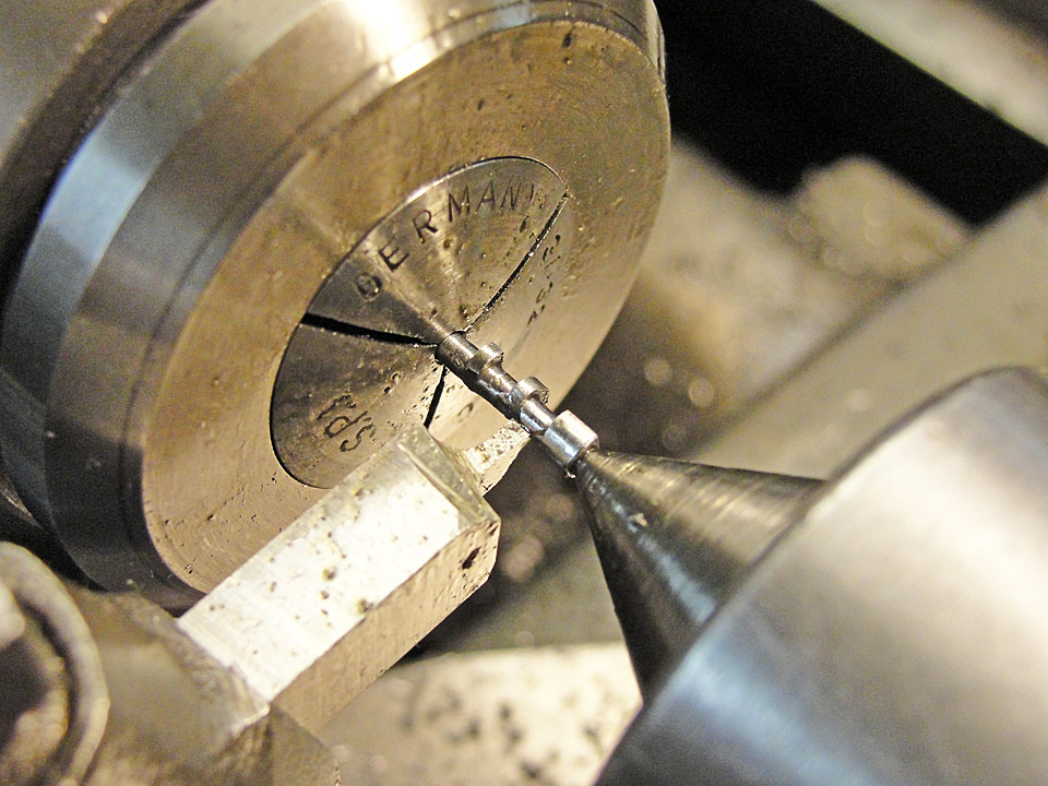
Alas, all I had for collets was the one beat-up step chuck
shown in these images. I also acquired a ball bearing Derbyshire
headstock, but that one has no key for a collet and no collet drawbar.
Lots of work to be done !
|
| Lucky me got a complete threading attachment at a
bargain, so I installed it, starting by tapping the center hole in the
lathe bed No.10-32, using the base plate of the attachment as a
template to spot the two 0.125 inch holes for the dowel pins, drilling
and reaming them, and making a thick paper "gasket" to compensate for
the spheroidal shape of the end of the bed and get a solid mounting of
the base plate. |
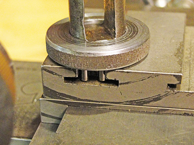
With fear and trepidation I lined up the gear
supplied with the threading attachment in my South Bend lathe's
four-jaw chuck, got it centered and free of wobble to less than 0.001
inch with a dial indicator, and bored it 0.001 inch oversize. On
the Derbyshire lathe's spindle, there is no perceptible runout or
wobble, and the gears mesh smoothly with no variation in noise during
running. Note the split in the center bushing.
|
The stud gear slides smoothly onto the rear end
of the lathe spindle and clamps easily, once I replaced the No.6-32
slotted-head set screw with a socket head set screw.
Then I dragged out the countershaft and scraped off a
multi-decade accumulation of lard (?) oil to reveal the beauty shown
below:
|

|

|

The lathe's two pedestals are meant to hold the lathe onto
a bench with a pair of two-part cap screws, which will have to be made
when mounting time comes about. Right now, it's just a stud at
one end.
|
 The needed smaller
banjo was a nice milling project. The only
lathe work was driling and boring the hole for the stud that the banjo
has to fit. I re-used the clamping screw after drilling and
tapping the appropriate cross hole and then splitting the bottom end of
the banjo. The needed smaller
banjo was a nice milling project. The only
lathe work was driling and boring the hole for the stud that the banjo
has to fit. I re-used the clamping screw after drilling and
tapping the appropriate cross hole and then splitting the bottom end of
the banjo.
Both the new banjo and the original one are steel, but the
original banjo was polished and then nickel plated. I checked
with a
magnet, as it seemed to be brass at first ...
Reducing the thickness of the slotted portion was an
interesting problem, which I solved by gripping the big end of the
banjo in the Atlas MM's vise and suporting the thin end of the banjo on
an adjustable parallel while the banjo was cantilevered over the MM's
table.
I cut the slots with a 1/8 inch diameter end mill, plunge
cutting at the ends of the slot and feeding back and forth between
stops about 0.030 deep at a time.
|

The longer banjo reaches just past the edge of the 60-tooth spindle
gear; I had to reduce the width of that gear by about 50 mils so it
would fit between the two gears in the first compound gear.
Compare the image at left with the image in the row
immediately above this row of images of the original banjo and ad hoc
No.5-40 cap screw needed to get the first gear in the compound to reach
the 60-tooth gear.
Next, I faced the problem of how to disengage the drive to the
lathe's tool rest in a convenient manner. Remember, there are no half
nuts on a jeweler's lathe !
|
The first method I tried was to put an unused
banjo to work as a stop to limit the back travel of the last banjo in
the gear train.
|
Here's how the last banjo rests against the
banjo that has the stop in place - that's just a repurposed idler gear
stud.
|
Now it's easy to loosen the clamp
screw on the last banjo and then swing the last two gears out of mesh;
or back in mesh.
|

|

|

|
It bothered me that there was no mechanism for
disengaging the drive to the compound slide other than moving the gears
as described in the row above.
Below at the top is the original drive shaft; note that
the two U-joints are not accurately aligned.
Next is my extension drive shaft and the start on the
engaging mechanism. Below that is the 0.032 inch thick, 0.625
inch
diameter HSS milling cutter that made the 0.042 inch wide slot on my
Atlas MM.
|
The cam that one turns to engage and disengage the
drive is shown in process below, held in a 3/32 inch collet to have the
center "throw" turned down to fit inside the slot in the extension
drive shaft.
I made no alterations to the original drive shaft; that
way I
could start over if I made any mistakes.
|
Here's how that cam works. The slot in
the closest cam enables me to rotate the key down into the slot in the
extension driveshaft. There's an over-center stage which keeps
the cam
engaged while driving the feed screw.
In the lower image I have disengaged the key by rotating
the cam 180 degrees counterclockwise. Now the feed screw turns
independently of the driveshaft.
A few "oops" cuts are evident but inconsequential.
|
Eventually I extended the keyway in my driveshaft extension and shortened
it by an inch so that the compound cross slide could be set closer to
the headstock.
The completed driveshaft assembly is shown below. I also
offset the slot in my driveshaft extension from its keyway to
compensate for the error in alignment of the original U-joints. I
could have made the offset greater, but it's good enough for now.
|

|
|


|

|
The lantern style toolpost that I fit to the
top slide of the compound has no rocker, so I made a screw-type height
adjuster.
|
The internal thread was by far the more
difficult; I left a rim on the male portion of the height adjuster so I
could grip it while fitting the thread.
|
The rim is gone now that the threads fit
smoothly. The pins eliminate the need for that rim so I can rotate just
the upper portion.
|
At left and below are the height adjuster's
extreme high and low positions, which are about an eighth of an inch
apart.
|

|

|

|
|
Threading is easier and produces better surface
finishes on the flanks of the threads if one feeds the 60 degree tool
at 29 degrees from the axis of the workpiece. On a conventional
lathe with a tool carriage, cross feed slide and adjustable angle top
slide, this is an easy matter to arrange for either external or
internal threads. On this lathe, there is no carriage, and the
top two slides are fixed permanently at ninety degrees to each other,
so the 29 degree offset is achieved by setting the bottom slide at 29
degrees and the upper slides parallel to the work axes.
|
I made a semi-permanent internal threading
setup by making a new fence with the 29 degree offset built into its
integral key that engages the slot in the bottom of the bottom
slide.
The fence also has the side facing the lathe bed machined at 30 degrees
from the vertical to engage one of the faces of the prismatic ways.
External (i.e., male) threads are to be handled without
changing the 29 degree fence by making another
tool holder with a slide motion built in, like I the one I made for the
Goodell-Pratt No.29-1/2 lathe.
|
I tried to set the vise of the Atlas milling
machine at 29 degrees when I milled the integral key, but it came out
closer to 30 degrees, so I made an approximate adjustment when I
machined the 30 degree beveled face of the fence in my South Bend
shaper. The result is shown below - just a little over 29 degrees
on the protractor of the Derbyshire compound.
|

|

|
 It
is very difficult to read the degree markings on the Derbyshire
slide because the marks are mostly underneath the top slide.
You'll have to view this image full size to even begin to see the zero
line and its relationship to the calibrated angles. It
is very difficult to read the degree markings on the Derbyshire
slide because the marks are mostly underneath the top slide.
You'll have to view this image full size to even begin to see the zero
line and its relationship to the calibrated angles.
|

|


|

|
Here's the slide I made for external threading
in the Derbyshire lathe.
There was less vertical room here than for the slide I
made for the Goodell-Pratt lathe, so the arrangement is a little
different. Both the top and the bottom portions of this slide
have slots to fit the 3/16 inch tool bit. I also made a cup
follower for the 1/4-28 screw that acts to feed the bit into the
workpiece, because the brass ring tilted too much.
|
Note in the third column above that there is plenty of
"meat"
above the tapped hole for the 1/4-28 screw on which to clamp the
slide. The intended angle, i.e., less than 30 degrees, causes the
right-hand side of the 60-degree bit to cut a much thinner chip than
the left-hand side. This keeps the two chips from interfering with each
other and also keeps the right-hand chip from forcing the tool slide
ahead of the proper longitudinal feed rate.
I already had a T rest, but I had to make the
saddle shown below. I hand scraped it to fit the ways of
the Derbyshire lathe and also made the T bolt and clamping nut.
|
The saddle allows one repeatedly to adjust the
lateral position of the T rest without causing localized wear to the
bed of the lathe.
The
T rest is also extremely snugly held with little
turning effort needed on the clamping nut.
|
I was in a quandary about driving the lathe (as
motors are pretty dear on the Internet) but then I rediscovered an old
pedestal fan motor made by Westinghouse a long time ago. It
needed a new cord and some brushing out of accumulated oily dust, but I
got it back together and running smoothly on 2.0 amps of 110 volt
current. Luck was with me, as it turns in the right direction.
|

|

|
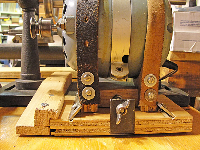
There are no mounting lugs, so I
strapped it onto a wooden
cradle cushioned with jute weatherstripping; those are the remnants of
the belts used to drive another project.
The two metal strips serve as ersatz dovetails to hold
down the motor, yet permit adjustment of the belt tension.
The 3/8 by 17 inch long V-belt arrived after this image
was made but functions OK, albeit a little stiff. Perhaps that is
good - it is very hard to stall the motor, once it's been started.
|
|
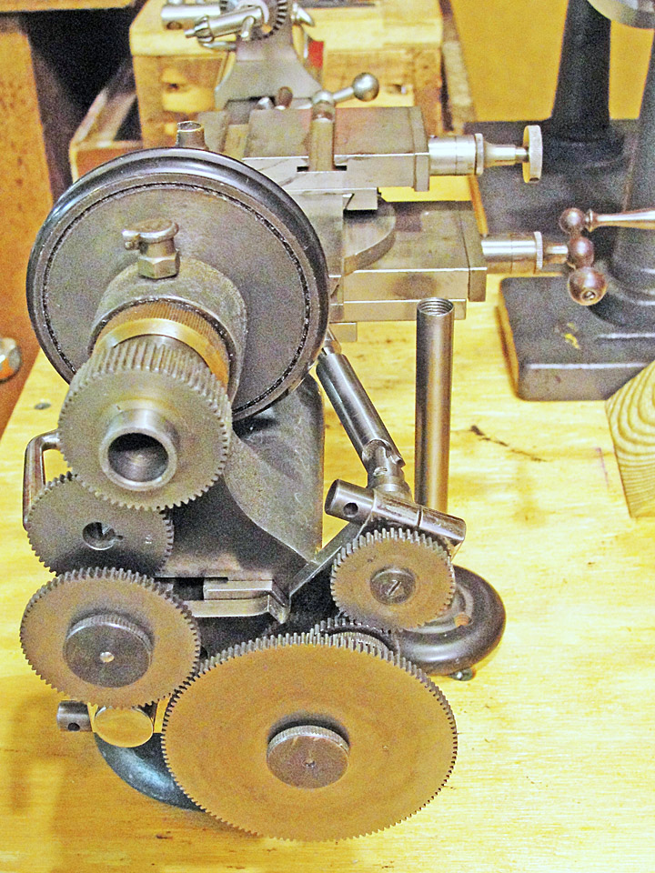


 The threading
attachment comes with three banjoes, two
right handed and one left handed.
The threading
attachment comes with three banjoes, two
right handed and one left handed.