
|

|
Once
I
got
all
the
grime
off
of
this
old
indexing
head, I realized that
it had the potential to do differential indexing, as the shaft (driven
by the mitre gears off the worm-driving shaft to which the crank is
attached) is parallel to the spindle when the spindle is aligned
horizontal, i.e., parallel to the base of the indexing head.
|
In
the
image
above
the
tail
of
the
spindle
is
threaded
to affix the
indexing drum described in the device patent (U.S. Patent No. 432,621)
and direct indexing is done by locating the drum with the index pin at
the bottom of this image. I found no damage other than dings and
scratches that couldn't be fixed with a triangular file. I adjusted the
worm easily.
|

|

|
|
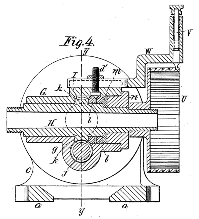
The text of U.S. Patent No. 432,621 reveals
that the inventor Frederick Holz did not contemplate differential
indexing - just spirals and plain indexing, either with the drum (image
at far right) or with the crank and disk of circles (above).
|
Figure 5 from the Holz patent shows how the
worm gear is adjusted for backlash - easily accomplished when the head
is rotated in its trunnions so that the spindle nose faces straight
down - and how the spindle is clamped by the knob at K'.
|
The drum U
is missing from my example of the indexing head, but you will see that
I have made a rearward-facing extension of the spindle which will
accommodate a new drum made from an old flat-belt pulley. What
are the drum's specific hole counts ?
|

The spindle extension shown in place at left is
entirely one piece, with a 1.375-18 thread at the large end to fit the
rear of the spindle and a 1/2-13 thread at the small end for the
clamping nut that affixes the South Bend size 18 diametrical pitch
gears (0.563 inch bores) that I'm currently making. There's room
for two thicknesses of gears (i.e., 0.375 times two plus a spacer)
because the spindle gear is often called upon to drive a compound gear
to effect the necessary ratios for differential indexing. The
T.I.R. of this extension is 0.001 inch, whch I achieved by doing most
of the boring & threading between centers or with a steady rest and
center. The central thread is 1.500-8 to fit South Bend headstock
accessories and to affix the new drum, which is moved back close to the
change gears to maximize the strength of the spindle extension. I
cleaned up the spindle's threads with a three cornered file until the
extension would thread onto the spindle by hand. The ID also fits
closely (0.001 inch) to the OD of the unthreaded portion of the spindle.
The nut seen on the worm shaft at lower left was frozen to
its threads because it had been improperly tempered (i.e., not at all)
and had cracked. Luckily, I found a replacement that is sound and
nicely made.
There's no place on the housing for the worm shaft to
which a banjo can be attached to support the change gears, so I'll be
making a separate frame that attaches to the machine table to which the
brackets for the change gears will be clamped. I did find a
thread on Practical Machinist that involved the sale
of
a
dividing head like this one that was outfitted for differential
indexing with a bracked held by the T-slot for the direct indexing
pin bracket and a bearing on the spindle extension.
My gear-making task is made a little harder because the diameter
of the worm gear shaft is 1.250 inch.
That precludes affixing 18DP gears with fewer than 30 teeth. I've
cut most of the blanks for the gears from steel bar stock (up to three
inches) or Class 40 cast iron in continuously cast bars four inches and
six inches in diameter. The six inch piece was six inches long,
and the four inch piece, four inches long. I've converted all of
one and all but 1/4 inch of the other piece entirely to gear blanks or
index-plate blanks (for two other projects) plus a huge pile of chips.
|
 |

|
The OD turning and facing operation at upper left was being done on the
second or third blank. Note that the 5-1/8 inch diameter cast iron
round barely clears the compound of this nine inch lathe. A six
inch OD piece would have to be worked on with a boring bar and overhung
from the chuck, making work on pieces this large not such a good idea.
The image at upper right was made after I had made a large number
of blanks. I found that I could cut the blank nearly entirely
free with this cut-off blade by stopping the lathe every so often and
extending the blade farther from its holder. Then I could simply
break the last quarter inch by prying gently with a screwdriver.
Yes, there was considerable chattering until I learned to
adjust the blade slightly below center; if it was at or above center it
screeched loudly. With the blade below center I could feed it
into the cut as long as that required some effort; once it started
feeding in too easily, I prudently stopped the cut so as not to let the
workpiece climb on top of the blade.
I sharpened the cutoff blade before every cut.
|
|
|
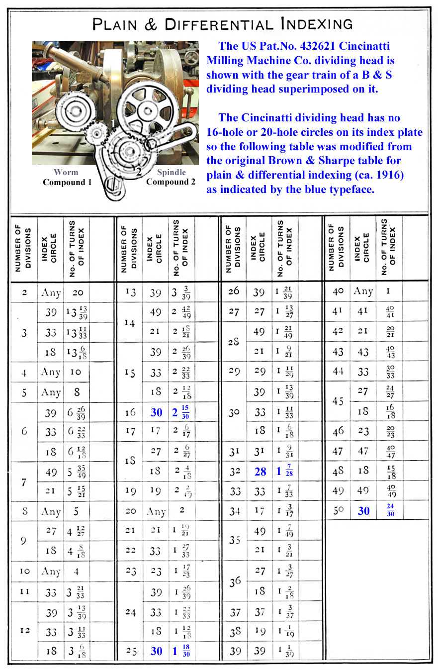
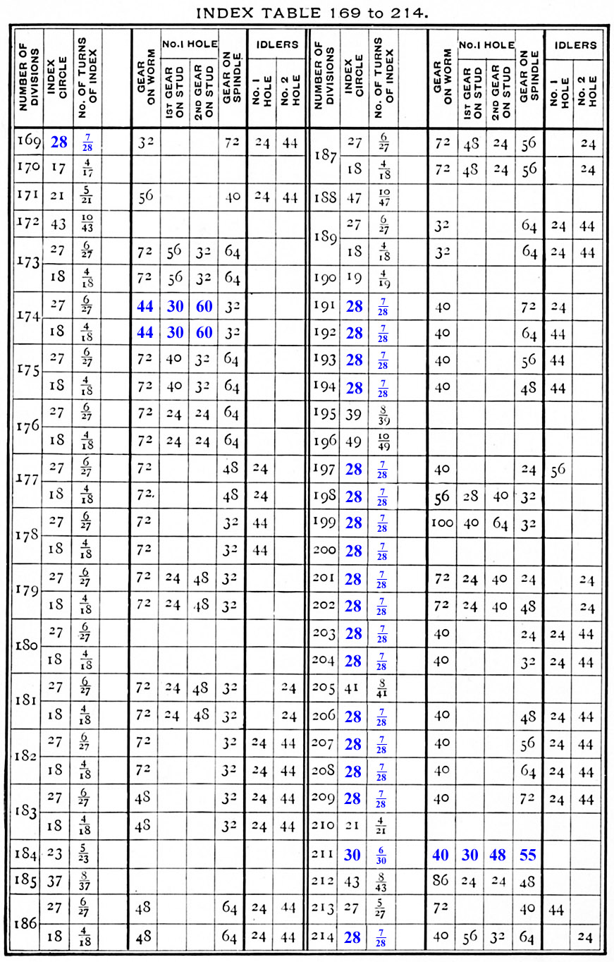
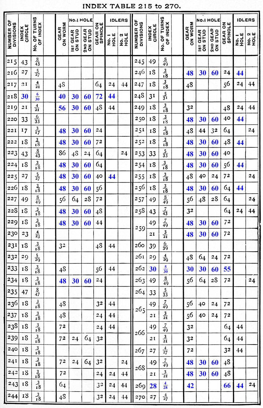
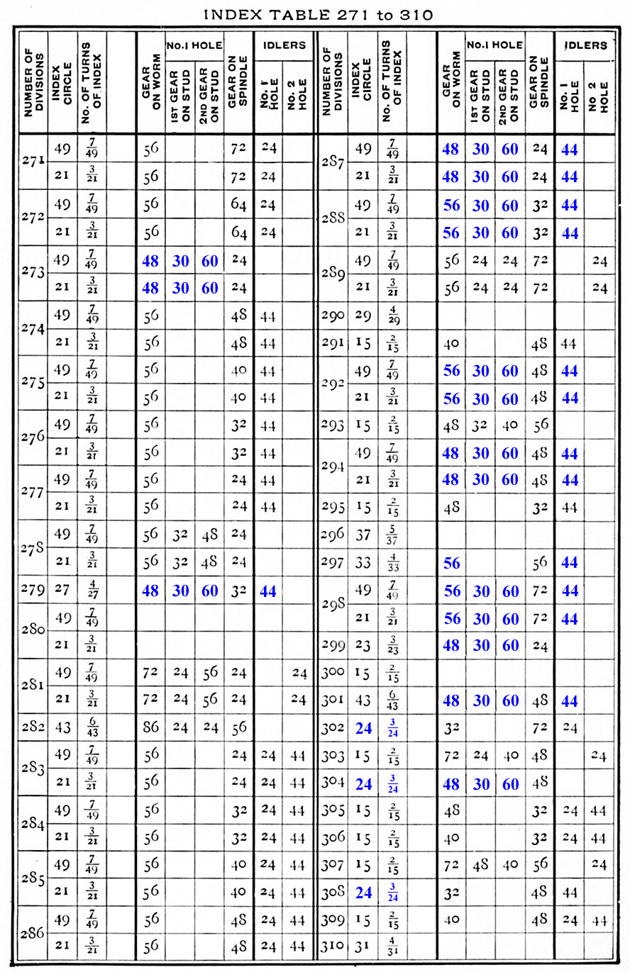
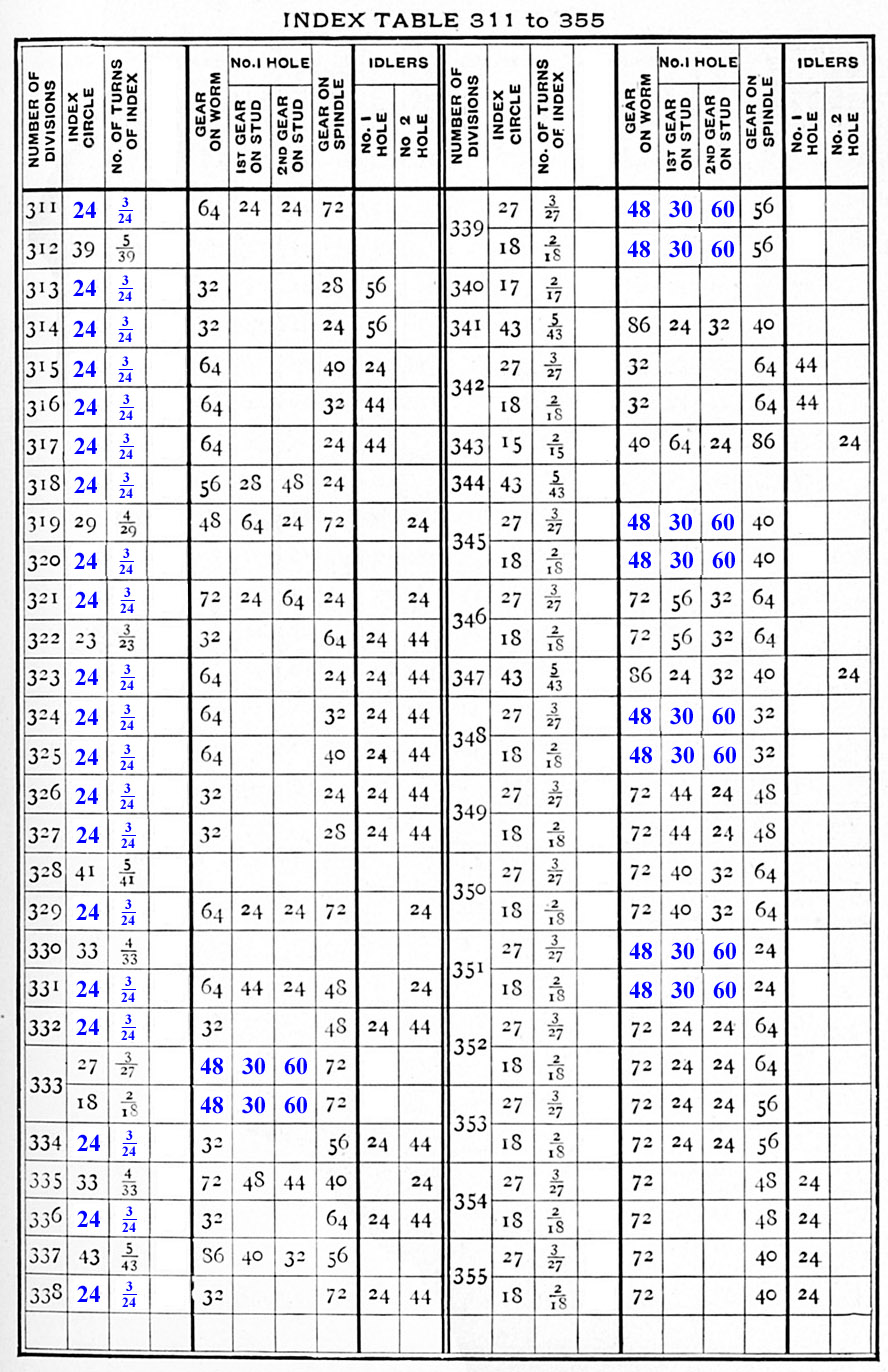
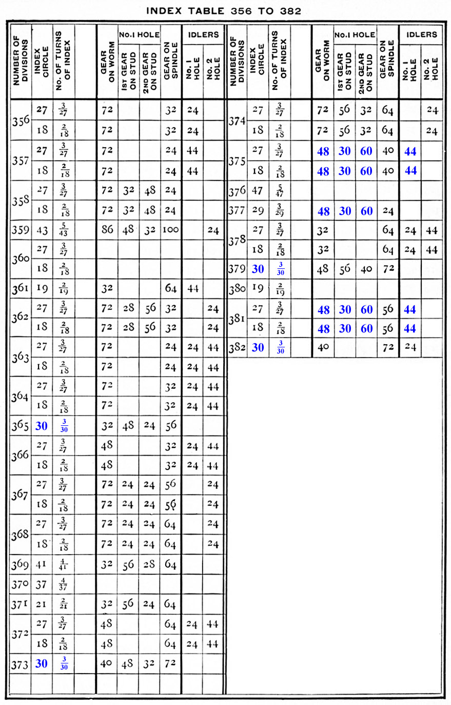
The
Cincinnati dividing head has a limited number of hole circles;
specifically, it is missing the 20-hole and 16-hole circles, so I have
modified the classical Brown & Sharpe Plain & Differential Indexing
tables (from the 1916 edition of Milling
and
Milling
Machines published by Brown & Sharpe Mfg. Co. in
Providence, RI) to accommodate that deficiency and also to omit use of
24 and 28 tooth gears on the worm shaft. In the tables below, the
modifications are in blue typeface. In Mozilla-type browsers you
can right click on an image to see it full size. Don't try these at
home without checking the amount of revolution for one division with a
dial indicator or vernier protractor and a level; there are no
guarantees that the blue numbers are correct ! I did find one
typo in the B&S table: for 83 divisions, which appears to ask for
10
holes out of 20 on a 26-hole circle; that's become 15 holes out of 30
on a 30-hole circle below.
|
|
 |
 |
 |
 |
 |
 |
 |
Sample Calculations.
Brown & Sharpe's engineers spent a lot more time than I have to
work out these ratios so as to minimize the need for many gears.
I have not been able to reproduce their logic, but the following
examples seem to work OK, once one gets the rotations correct.
|
128 divisions:
128/3 =
42-2/3 ...
2-2/3 = 8/3, so spindle to worm ratio is to be 8/3 or 64/24 teeth,
using available gears. 24 tooth gear is N.A., so use 64/48 times
60/30 compound gears. Add idler(s) so index plate turns 42-2/3 times
while spindle is turning one revolution. To get 128 divisions,
turn crank 13 of 39 holes (one-third revolution) for each division.
Three times 42-2/3 = 128.
|
211 divisions:
211/5 = 42-1/5 ... 2-1/5 = 11/5, so spindle
to worm ratio is to be 11/5 or 55/25. 25 tooth gear is N.A., so use
55/50 times 8/5 = 55/40 times 48/30 compound gears. Add idler(s)
so index plate turns 42-1/5 times while spindle is making one
revolution. To get 211 divisions, turn crank 6 of 30 holes (one-fifth
revolution) for each division. Five times 42-1/5 = 211.
|
269
divisions:
269/7 = 38-3/7 = 40 - 1-4/7 ... so spindle to worm ratio is
to be 11/7 or 33/21 = 33/42 times 60/30. Add idler(s) so index
plate turns 40
times less 1-4/7 revolution while spindle is making one
revolution. To get 269 divisions, turn crank 4 of 28 holes
(one-seventh revolution) for each division. Seven times 38-3/7 =
269.
|
|
|