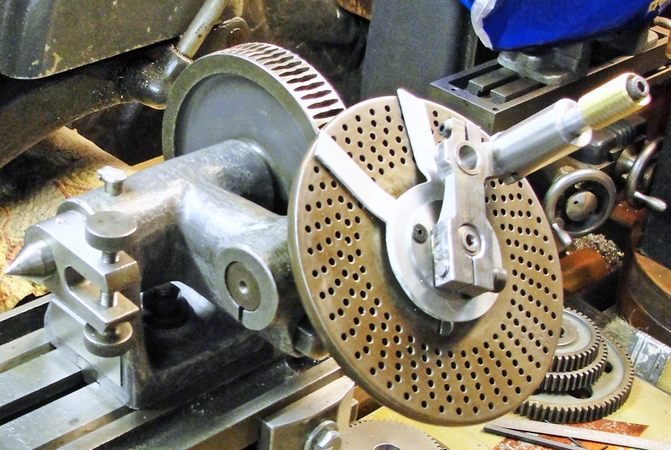
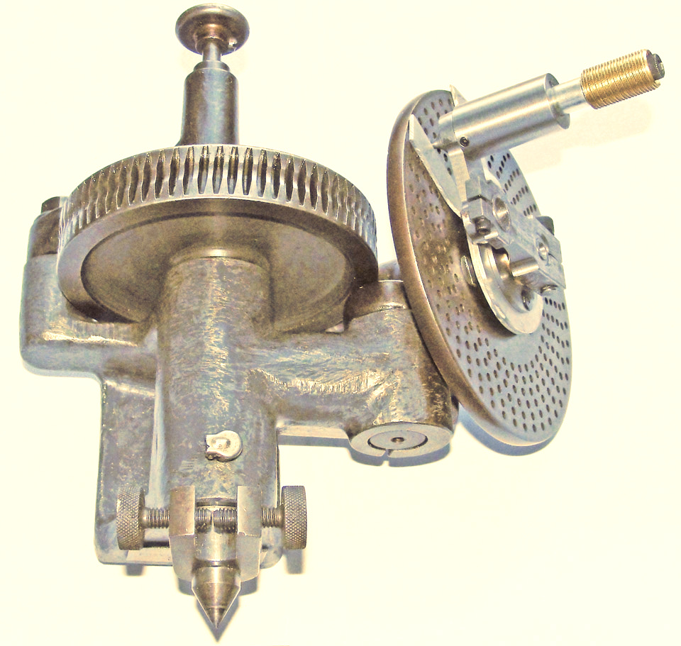
This Brown &
Sharpe set of indexing centers was intended for use on a
grinding machine, as there is provision only for working between
centers; the main spindle center is permanently attached.
However, the existing index plate, made integral with the worm wheel,
permits only a limited number of divisions for such things as spur
gears, which is the use for which I have upgraded the device.
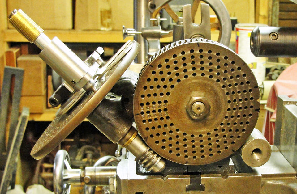
This view shows the back side and indexed worm gear of the
centers along with both the old worm gear and plain crank and the new
worm gear and its articulated crank and removeable index plate.
The original pin arm was left in place but is not needed
in order to operate the indexing mechanism.
The old worm is shown lying underneath.
|
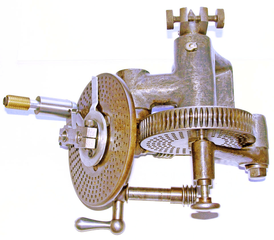
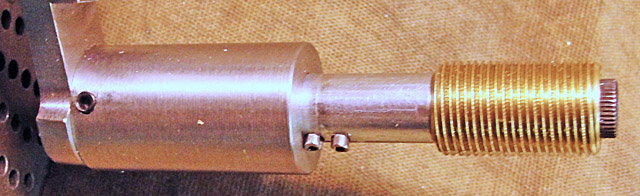
 The
bottom view here shows how the newly adapted indexing disk is
attached with a carrier that is press fit over the end of the worm
shaft's housing.
The
bottom view here shows how the newly adapted indexing disk is
attached with a carrier that is press fit over the end of the worm
shaft's housing.
I made no changes to the original casting of
the indexing centers; the new parts can be removed and the old parts
replaced with no repairs or adapters necessary.
The new worm was made as an Acme-threaded 6 tpi screw of
the same outside diameter as the original worm, even its hourglass
profile.
I ground the worm's threading tool to match a B&S Acme
single-point threading tool gauge. The carrier is steadied by the 0.500
inch diameter tool steel shaft of the new worm.
|
 The
worm
shaft
has
bronze
thrust
bearings
at
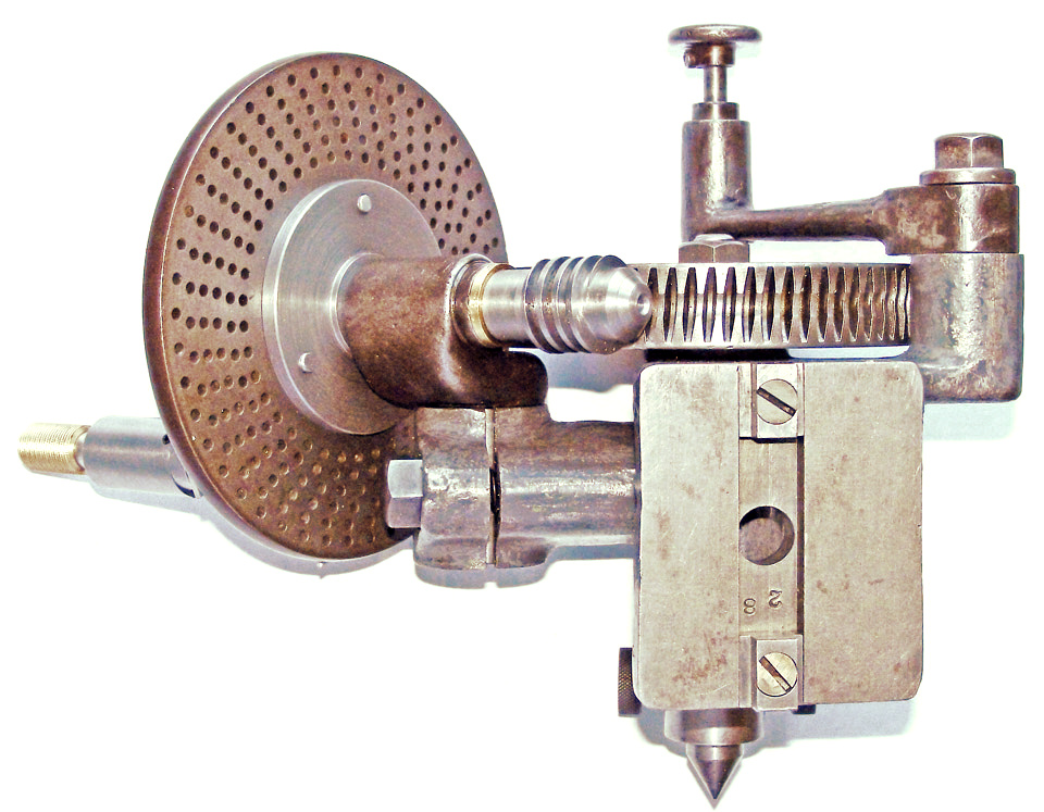
each end, and the end
play/backlash is adjusted by rotating the articulated crank on the
1/2-13 threaded end of the shaft and then clamping it with the 1/4-20
socket head cap screw.
The
worm
shaft
has
bronze
thrust
bearings
at
each end, and the end
play/backlash is adjusted by rotating the articulated crank on the
1/2-13 threaded end of the shaft and then clamping it with the 1/4-20
socket head cap screw.
Another socket head cap screw, No.5-40 size, easily clamps
the articulation joint of the crank so that the pin can be reliably
dropped in the chosen circle of index holes.
The aluminum sector arms are clamped by three No.6-32 size
flat head socket screws and rotate on the two steel plates that the
clamp screws engage. The assembly rotates on the disk carrier; friction
is applied by an O-ring sandwiched between the two steel plates.
The pin housing is
hollow; the two rollpins act
to hold the pin in the disengaged position and also to keep the
pin from rotating away from the guiding keyway. |
|
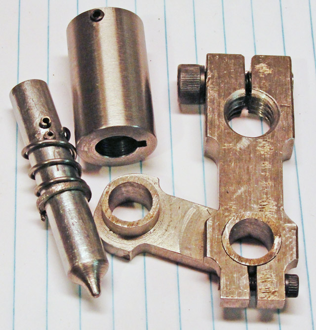 The short spring is completely compressed when the
pin is withdrawn to the position in the first image above. When the pin
is engaged with a hole in the index disk, the spring is completely
extended. The split collar against which the spring presses at the
bottom is let into a groove cut in the pin. The short spring is completely compressed when the
pin is withdrawn to the position in the first image above. When the pin
is engaged with a hole in the index disk, the spring is completely
extended. The split collar against which the spring presses at the
bottom is let into a groove cut in the pin.
After this picture was taken, I bent the upper end of the
spring so it could not get past the bottom rollpin.
The short arm of the articulated crank has an integral
boss at each end; the central hole in each boss lets the arm be carried
on a 3/8 inch diameter mandrel for machining. |
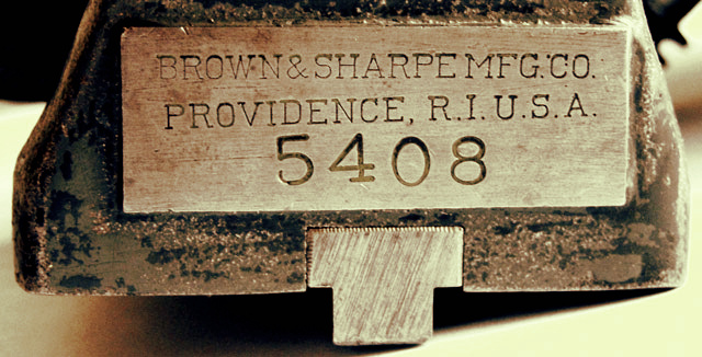 The Brown & Sharpe maker's marks do not
give a model number; this indexing center pair was not made for one of
Brown & Sharpe's many milling machines. The Brown & Sharpe maker's marks do not
give a model number; this indexing center pair was not made for one of
Brown & Sharpe's many milling machines.
In the 1916 Brown & Sharpe General
Line Catalog, it's the 4-3/4 inch indexing centers for the No.'s
2, 12 & 13 surface and universal & tool grinding machines.
|
|
The worm wheel
has 75 teeth. The following table gives the indexing data calculated
from the ratio of {75/(No.ofTeeth)}.
I have three disks with circles of (18, 24, 28, 30, 34 & 37), (38,
39, 41, 42, 43, & 46) and (47, 49, 54, 58, 62, & 66) holes.
Underlined circles must be created; best candidates are circles of 44,
52, 56, 64, 68,76, 82, 86, 88, 92, 94, 98, and 127 (the last is for
metric
conversions).
The worm wheel itself has indexing circles of 24, 28, 32, 36 & 40
holes; the worm is a single start type.
Counts greater than half a circle can be reduced
by moving the sector backwards
by the complement of the turns ratio.
Example: for 39 teeth, go two
turns less 3/39th of a turn.
No. of Teeth
|
Circle
|
Turns
|
No. of Teeth |
Circle |
Turns |
No .of Teeth |
Circle |
Turns |
No. of Teeth |
Circle |
Turns |
No. of Teeth |
Circle |
Turns |
No. of Teeth |
Circle |
Turns |
No. of Teeth |
Circle |
Turns |
2
|
18
|
37+9/18
|
16
|
64
|
4+44/64
|
30
|
18
|
2+9/18
|
44
|
44
|
1+31/44 |
64
|
64
|
1+11/64
|
86
|
86
|
75/86
|
116
|
116 |
75/116 |
3
|
any
|
25
|
17
|
34
|
4+14/34
|
31
|
62
|
2+26/62
|
45
|
18
|
1+12/18
|
65
|
39
|
1+6/39
|
88
|
88
|
75/88
|
120 |
24
|
15/24
|
4
|
24
|
18+16/24
|
18
|
18
|
4+3/18
|
32
|
64
|
2+22/64
|
46
|
46
|
1+29/46
|
66
|
66
|
1+9/66
|
90
|
18
|
15/18
|
124
|
124 |
75/124 |
5
|
any
|
15
|
19
|
38
|
3+18/19
|
33
|
66
|
2+18/66
|
47
|
47
|
1+28/47
|
68
|
68
|
1+7/68
|
92
|
92
|
75/92
|
127
|
127 |
75/127 |
6
|
18
|
12+9/18
|
20
|
24
|
3+18/24
|
34
|
34
|
2+7/34
|
48
|
64
|
1+9/16
|
70
|
28
|
1+2/28
|
94
|
94
|
75/94
|
128
|
128 |
75/128 |
7
|
49
|
10+35/49
|
21
|
42
|
3+24/42
|
35
|
49
|
2+7/49
|
49
|
49
|
1+26/49
|
72
|
24
|
1+1/24
|
95
|
38
|
30/38
|
130
|
52 |
30/52 |
8
|
24
|
9+9/24
|
22
|
44
|
3+18/44
|
36
|
24
|
2+2/24
|
50
|
18
|
1+9/18
|
74
|
74
|
1+1/74
|
96
|
64
|
50/64
|
132
|
132 |
75/132 |
9
|
18
|
8+6/18
|
23
|
46
|
3+12/46
|
37
|
37
|
2+1/37
|
52
|
52
|
1+23/52
|
75
|
any
|
1
|
98
|
98 |
75/98 |
135
|
54
|
30/54
|
10
|
18
|
7+9/18
|
24
|
24
|
3+3/24
|
38
|
38
|
1+37/38
|
54
|
54
|
1+21/54
|
76
|
76
|
75/76
|
100
|
24
|
18/24
|
136
|
136 |
75/136
|
11
|
66
|
6+54/66
|
25
|
any
|
3
|
39
|
39
|
1+36/39
|
55
|
66
|
1+24/66
|
78
|
52
|
50/52
|
102
|
34
|
25/34
|
140
|
28
|
15/28
|
12
|
24
|
6+6/24
|
26
|
52
|
2+46/52
|
40
|
24
|
1+21/24
|
56
|
56
|
1+19/56
|
80
|
64
|
60/64
|
104
|
104 |
75/104 |
144
|
144 |
75/155
|
13
|
39
|
5+30/39
|
27
|
54
|
2+42/54
|
41
|
41
|
1+34/41
|
58
|
58
|
1+17/58
|
82
|
82
|
75/82
|
108 |
108 |
75/108 |
145
|
58
|
30/58
|
14
|
28
|
5+10/28
|
28
|
28
|
2+9/28
|
42
|
42
|
1+33/42
|
60
|
24
|
1+6/24
|
84
|
28
|
25/28
|
110
|
66
|
45/66
|
148 |
148 |
75/148 |
15
|
any
|
5
|
29
|
58
|
2+14/58
|
43
|
43
|
1-32/43
|
62
|
62
|
1+13/62
|
85
|
34
|
30/34
|
115
|
46 |
30/46 |
150
|
18
|
9/18
|
|