|
Part I -
Adapting template gears with bores smaller than 3/4 inch to the Atlas
milling machine's indexing centers.
 Just as I did for
my Sebastian
treadle
lathe,
rather than making any permanent, irreversible changes to the Atlas
milling machine's plain indexing centers, I made an adapter to enable
use of the South Bend lathe's change gears (which mostly have a 9/16ths
inch bore) as templates. Just as I did for
my Sebastian
treadle
lathe,
rather than making any permanent, irreversible changes to the Atlas
milling machine's plain indexing centers, I made an adapter to enable
use of the South Bend lathe's change gears (which mostly have a 9/16ths
inch bore) as templates.
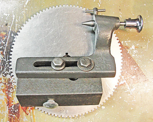
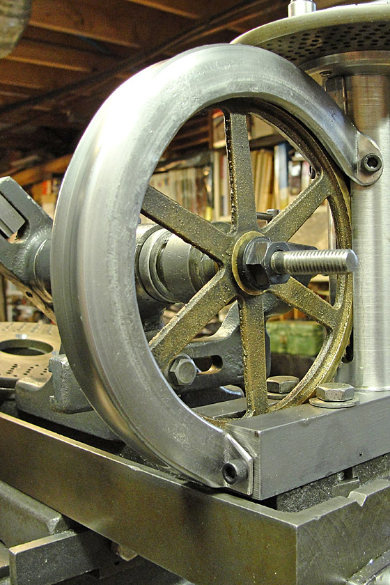
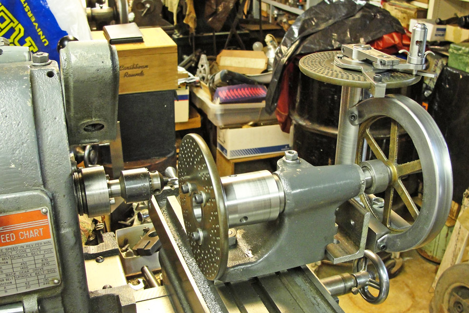
The adapter consists of a plug closely fit to the bore of
the
indexing center's spindle and incorporating a tapered collar that
matches the center bearing of the spindle, and which is clamped in
place by the indexing center's nut (shown sitting on the Atlas MM's
table).
|
 The
adapter
also
has a sleeve to match the bore of the gear being used
as a template to the diameter of the adapter plug.
The
adapter
also
has a sleeve to match the bore of the gear being used
as a template to the diameter of the adapter plug.
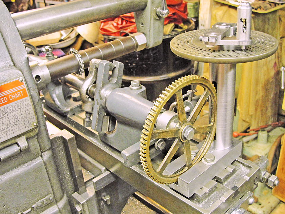
In the image at left, the adapter is holding a 100 tooth
change gear
(needed for making metric threads on the South Bend lathe) onto the
spindle of the Atlas milling machine's indexing centers. There is no
key used - the friction of the 5/16-18 clamping screw is sufficient.
Note the stops that I added to the longitudinal table
travel. held in place by the former gearbox screws.
|
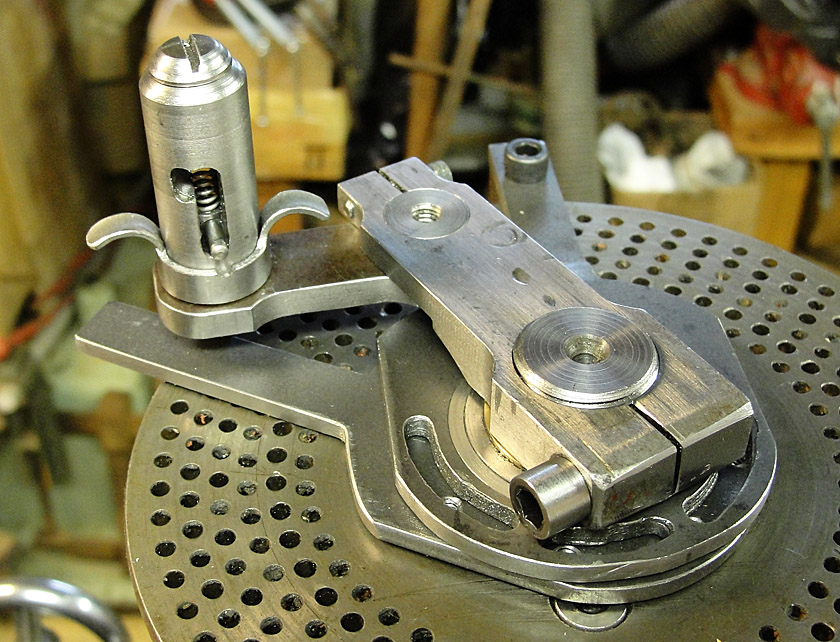
 Another
necessary
part
of
the above adapter is an angle plate that
holds the indexing pawl, which simply clamps to the table of the Atlas
milling machine.
Another
necessary
part
of
the above adapter is an angle plate that
holds the indexing pawl, which simply clamps to the table of the Atlas
milling machine.
I made a new pin for the indexing pawl which has a 14-1/2
degree
cone to match the pressure angle of the template gear. The Atlas
indexing centers come with a pin whose nose radius is a bit too large
for the smaller gear pitches.
The angle plate has three mounting holes for the pawl
carrier so
that it can be appropriately placed for any template within the range
of the milling machine.
|
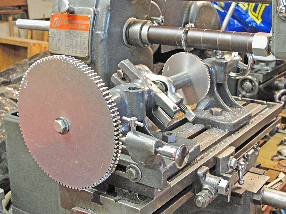
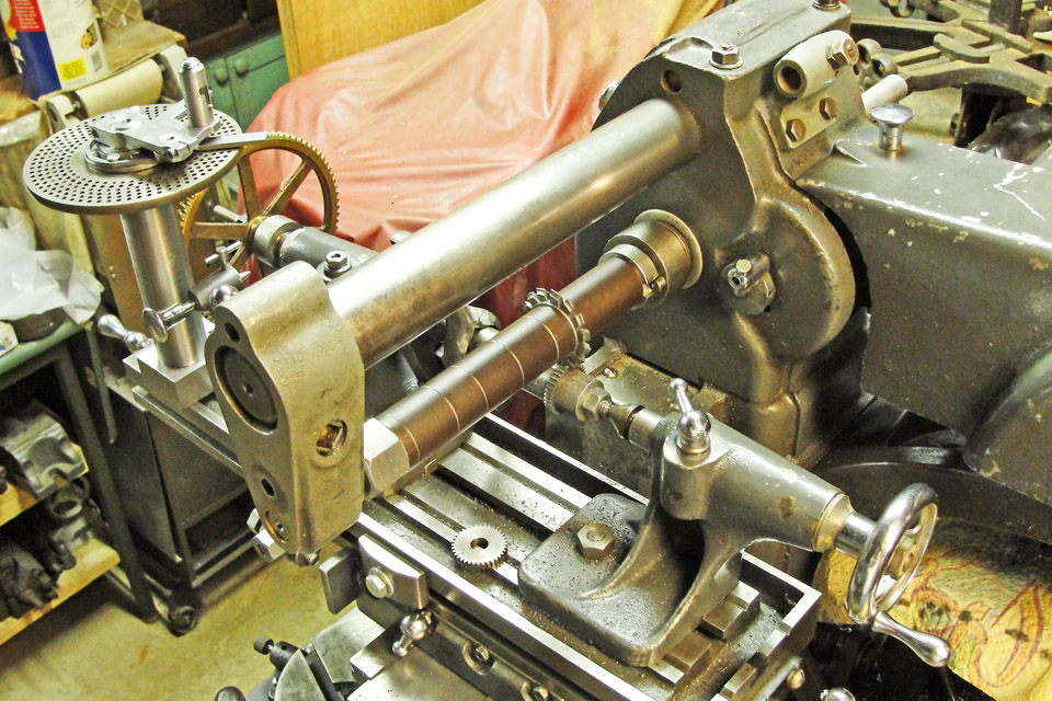
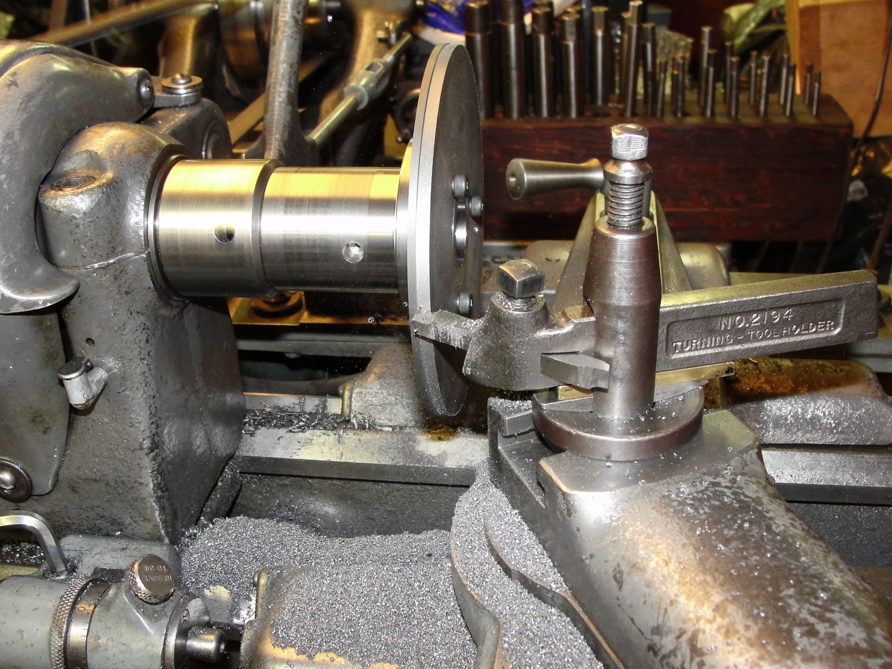
As seen in the image at left, even template gears which
the indexing
centers cannot swing over the table of theAtlas milling machine can be
hung over the end of the table.
The 100 toth gear being made here is 32 diametrical pitch,
intended for my Goodell-Pratt
29-1/2
"treadle"
lathe's
screw threading adapter.
|
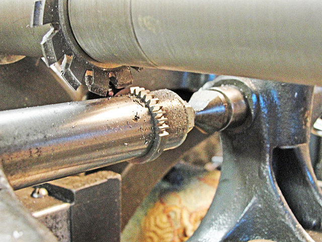
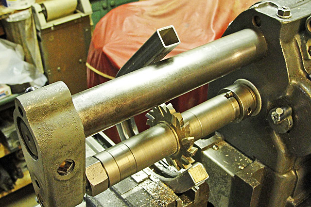
The 36-tooth gear shown in process at left is being made
on an arbor
which I made that would be stiffer than the tapered arbors used
previously, which do not hold the gear blank securely perpendicular to
the arbor axis and which deflect excessively in the smaller sizes, such
as 3/8 inch.
The arbor has a threaded extension sized to fit the gear
blank's
bore and a loose collar to facilitate making more than just one gear at
a time and to place the threads of the arbor outside the bore of the
gear blank.
|
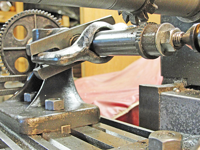
The arbor is driven by a lathe dog and is carried on the
two centers of the indexing head.
That's a 72-tooth template gear (from the set that came
with the indexing centers) in the background.
This arbor is far stiffer than a simple tapered arbor and
helps to
prevent most of the chattering that is created by interactions between
the arbor and the knee of the milling machine.
|
|
|
Part II -
Freeing the Atlas milling machine's indexing centers from the need for
templates.
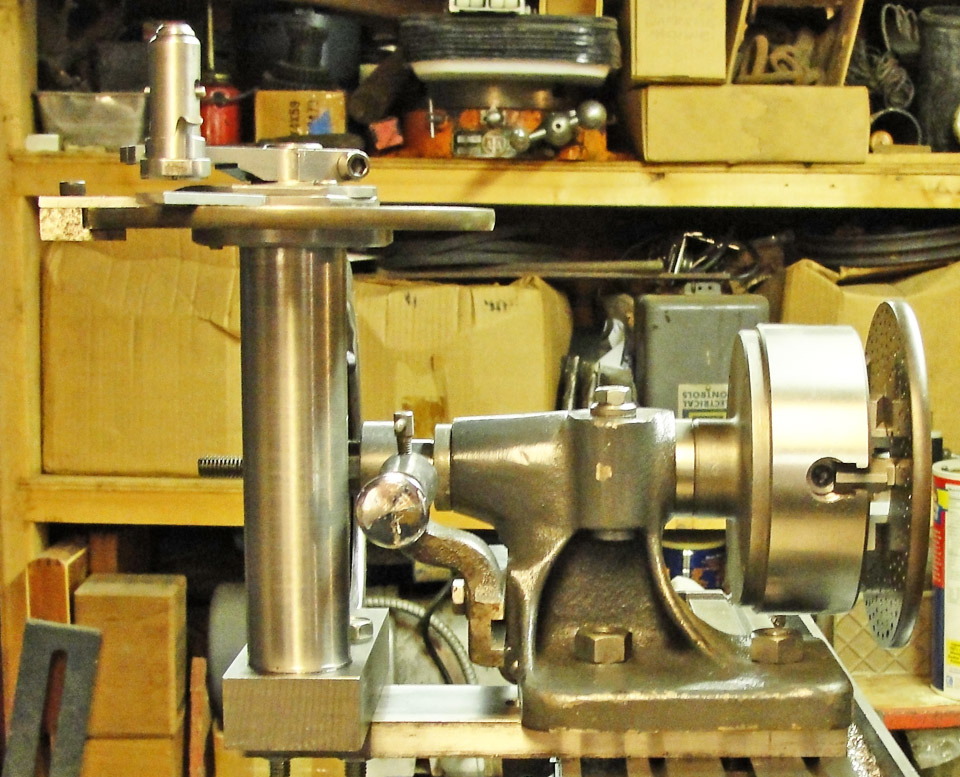
 While rummaging through my parts drawers in
search of 32 DP gears, I came across this 80-tooth worm gear.
That's just twice the number of teeth in a standard universal index's
40-tooth worm gear, so I decided to put my found gear to use. While rummaging through my parts drawers in
search of 32 DP gears, I came across this 80-tooth worm gear.
That's just twice the number of teeth in a standard universal index's
40-tooth worm gear, so I decided to put my found gear to use.
The 5/16-18 tpi cap
screw and plain washer did not hold
the
80-tooth worm gear securely, so I used a 5/16-18 tpi stud and flanged
nut
from the workpiece clamping set for the Atlas miling machine instead.
|
 The indexing plates came from a CRAFTS of NJ tailgating session, I
think ... or from a Cabin Fever auction ... I made the crank from
scratch, using the experience I gained from making a banjo for my Derbyshire
lathe thread cutting adapter.
The indexing plates came from a CRAFTS of NJ tailgating session, I
think ... or from a Cabin Fever auction ... I made the crank from
scratch, using the experience I gained from making a banjo for my Derbyshire
lathe thread cutting adapter.
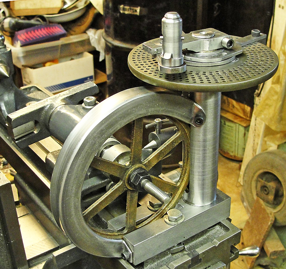
Shown at left is the first
assembly of the gear to the adapter
which I made that permits the gear to drive the spindle of the Atlas
milling machine's indexing centers without any permanent
modifications. The vertical cylinder is press fit to its base and
carries a 3/4-5 tpi Acme-threaded worm in bronze bearings.
|
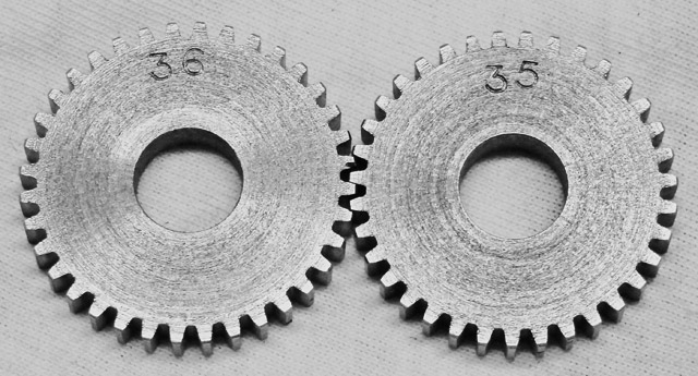
The 36-tooth 32 DP gear at far left was made using a
72-tooth Atlas gear as a template, whereas the 35-tooth gear to its
right was cut with the 49-hole index in the newly upgraded Atlas
indexing centers using one and 7/49 turns of the crank executed twice
per tooth.
The gears mesh perfectly !
|
Still to come:
I. A guard to protect the delicate 80-tooth cast bronze worm gear,
being made by bending a piece of 3/4 inch square steel tube to a ca.
2-1/2 inch radius and then milling a 3/8 inch wide slot around its
inner perimeter. The bending task is complete; I didn't break anything
or get too sore.
II. An accessory to protect my fingertips while lifting the indexing
pin of the crank. The present 1/8 inch cross pin's tips are too small
for the rather strong spring that forces the pin into the circle of
holes in the index plate.
III. I already made a clamp that prevents inadvertent movement of the
indexing sector, which can be disastrous when it occurs during cranking
of the worm while gear-cutting.
IV. Now I need a bunch of 5 inch diameter indexing plates ...
|
Part III -
The promised extras.
 The
gear guard started out as a 16 inch long piece of 3/4 inch square
welded tubing, which I was able to bend cold with the aid of a cheater
bar and a piece of heavy steel tubing that was just the right diameter
around which to form the more-than-180 degree curve of the guard.
A bar clamp allowed me to complete the bending task, as it let me bend
the tubing with my own hands without great effort. Of course, I
filled the tube with fine sand and hammered in oak plugs to keep it
inside. One of those plugs is visible above. I slotted the bent
tube with the Atlas milling machine.
The
gear guard started out as a 16 inch long piece of 3/4 inch square
welded tubing, which I was able to bend cold with the aid of a cheater
bar and a piece of heavy steel tubing that was just the right diameter
around which to form the more-than-180 degree curve of the guard.
A bar clamp allowed me to complete the bending task, as it let me bend
the tubing with my own hands without great effort. Of course, I
filled the tube with fine sand and hammered in oak plugs to keep it
inside. One of those plugs is visible above. I slotted the bent
tube with the Atlas milling machine.
|
 The slotting went uneventfully, as the tube's sides did not try to
clamp the sides of the 3/8 inch wide milling cutter. To center
the slot, I milled all the way around the guard and then reversed the
guard in the vise.
The slotting went uneventfully, as the tube's sides did not try to
clamp the sides of the 3/8 inch wide milling cutter. To center
the slot, I milled all the way around the guard and then reversed the
guard in the vise.
After that, it was just a matter of judiciously sawing
tabs into the ends of the guard to fit the shape of the housing of the
gear drive. Lots of filing and even some work with a jewelers saw to
avoid struggles with clamping the guard in the bench vise.
Lastly, I drilled the four attachment holes in the guard,
clamped the guard onto the housing, and prick punched the sites to
drill and tap the housing for No.10-32 tpi cap screws. I opened
up
the clearance holes to 17/64 and did have to file one attachment hole
oval to clear its screw. It's very rigid and guards the delicate
worm gear nicely.
|
The little cross pin that I used to lift the index plunger is
too small in diameter for my fingers, so I made a tubular lifter and
cut tabs from the tube as shown at left. Now it's easy to lift
and twist the plunger in order to latch it into place while cranking
the worm gear to the next index position with no risk of catching the
sector and moving it.
I also added a clamp to one of the sector arms as seen at the rear of
the right- hand arm in the image at left.
|
 The indexer is
adjusted for zero backlash when the housing
of the worm gear is clamped to the table of the milling machine. Then
the end play is taken out of the worm gear by loosening the crank's
clamp screw and screwing the crank down onto the upper thrust
bearing. Tightening the clamp screw of the crank takes up a
little more end play, so this is a trial-and-error process to eliminate
all the backlash in the indexing mechanism. The indexer is
adjusted for zero backlash when the housing
of the worm gear is clamped to the table of the milling machine. Then
the end play is taken out of the worm gear by loosening the crank's
clamp screw and screwing the crank down onto the upper thrust
bearing. Tightening the clamp screw of the crank takes up a
little more end play, so this is a trial-and-error process to eliminate
all the backlash in the indexing mechanism.
The gear guard not only protects the worm gear from
inadvertent impacts, it also shields the gear from chips, as they
cannot
land in the teeth of the worm gear. I do not have to remove the
guard while mounting/demounting the accessory.
|
Part IV - Making indexing plates
In order to drill the properly spaced holes in any new
index plates that I might make, I needed an adapter to present the disk
at right angles to the Atlas MM's spindle. I found a two inch
wide piece of half inch thick CRS which I draw filed flat to within
0.001 inch.
Then I drilled and countersunk two holes for 3/6-16 tpi
cap screws to clamp this plate to the table, installed two 5/16-18 tpi
studs and cut keyways in the plate for the indexing center's two 3/8
inch wide keys, and then fitted the worm gear accessory described above.
|
The Craftsman four inch chuck, while nicely made and fairly rigid,
doesn't hold the disk securely for drilling, so I made a dedicated
adapter threaded 1-10 tpi to fit the spindle nose of the indexing
centers by chasing the threads in my South Bend lathe and then
finishing the face and shoulder while the adapter was screwed onto
another 1-1/2-8 tpi to 1-10 tpi adapter that I made years ago.
|
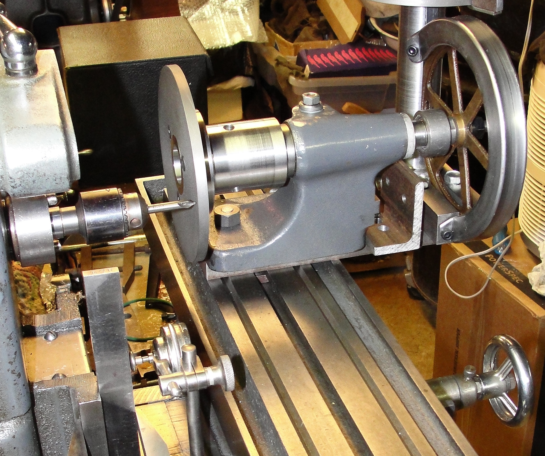
The worm-gear accessory is just one
way of indexing the holes in the planned disks. I can just use
another gear with a 3/4 inch bore right on the back end of the indexing
center's spindle, or a different size bore (such as the South Bend
lathe's 9/16 inch bore change gears) mounted on a suitable adapter made
for the 80-tooth worm gear accessory. In the image immediately
above right I have mounted the angle-iron adapter made for that latter
purpose onto the half-inch-by-two-inch CRS plate. For example, I
can use the 127-tooth, 48 DP gear for the Derbyshire instrument lathe
as the template for drilling the 127-hole circle in a blank indexing
plate. The holes in the 5.0 inch diameter indexing disk would
have to be smaller than 4.75Pi/127 = 0.115 inch in diameter in
order not to part the disk [simple solution added in November 2016: don't drill clear through
the disk !].
|
|
|
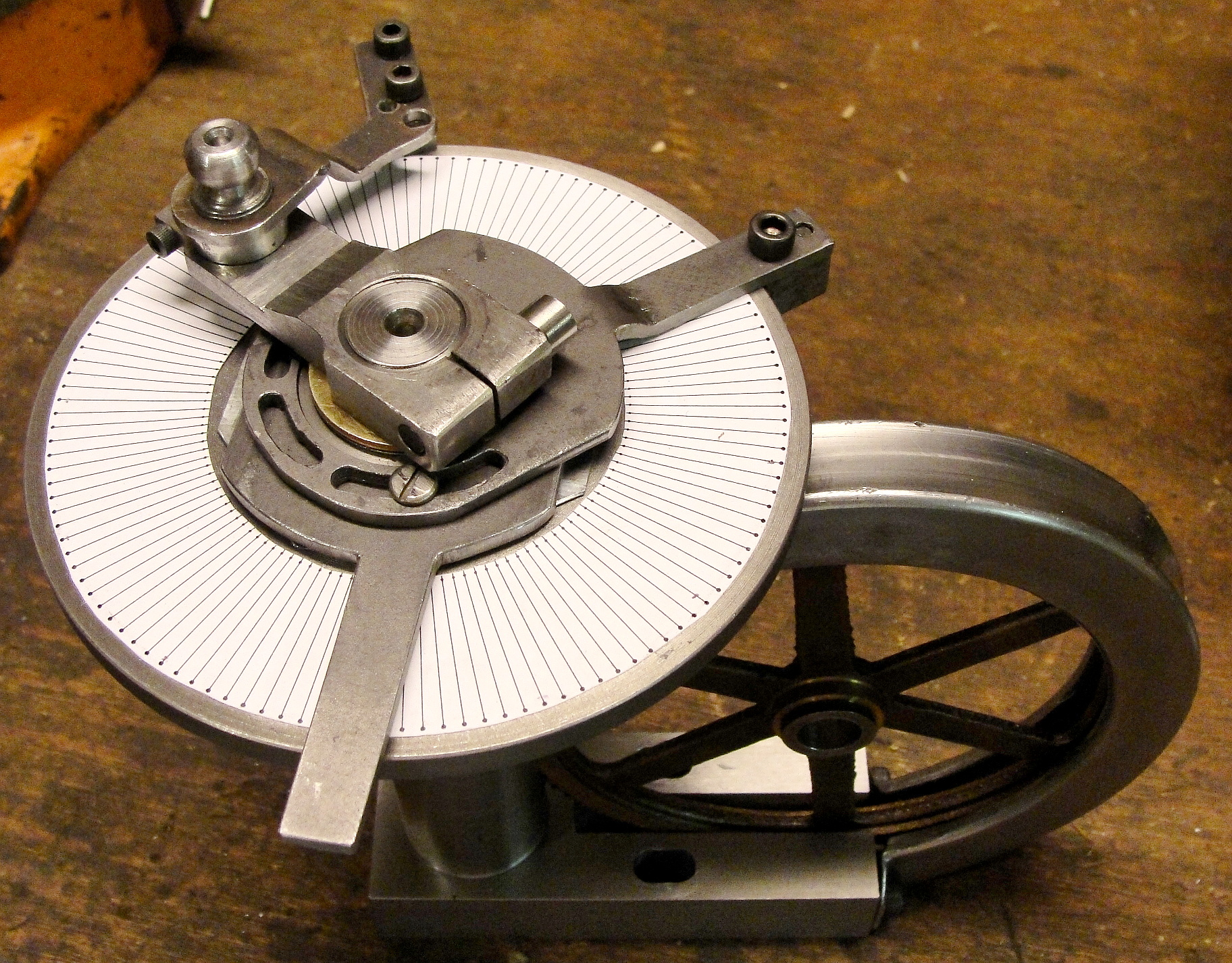
Here's my proposed solution:
Use a plotting program (here: PSI-Plot, running under Wine on a laptop
running linux) to lay out 127 dots in a circle slightly smaller than
the OD of the cast iron disk, with radial lines passing through each
dot. The template is attached to the disk with Scotch double-sided tape
and aligned within one-dot-width to the circumference of the disk; the
double-sided tape doesn't "grab" the paper, so it can be pushed around
with the dividers that I used to check the aligment and then pressed
into place, where the sector arms and their clamps don't interfere with
the paper.
|
Note: Right-click and select "view image" to see these pictures full size, whereupon the radial lines will look OK.
|
|
With the setup shown above, left,
the sighting tube that I had just attached to the crank arm was about
chin-high, so I had to use an angled dental mirror and (occasionally)
an LED flashlight to see the dots as shown approximately in the
photograph at right. This was easier than it looks, and I completed
drilling the 127 holes in about two hours.
|

|

|

|
In
the third image I have
re-plotted the 127 hole locations on a 4.64 inch circle, converted the white
background to transparency, and fitted the plotted circle's small white
dots to the image of the disk. I had to adjust the width and height
of the disk image to fit the calculated circle of holes because the Epson plotter may not
be as accurate as my PSI-Plot plotting program.
There are actually 127 holes in the disk !
|
My
next step will be to countersink these
1/16th inch holes to set the sector arms with my original indexing
setup, and then to drill another 127 holes in the second disk. Each
pair of the 127 holes lies on 0.115 inch centers. View the overlain
disk full size to view the hole alignments.
|
|

