|
Progress
to January 2005:
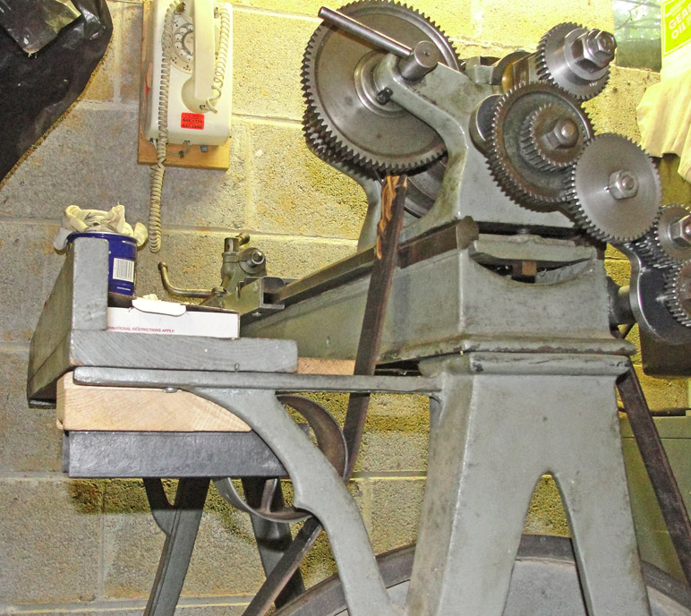
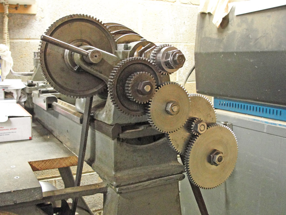
The lathe as shown at left has no
makers marks. However, one like it is
shown in Kenneth L. Cope's book,
American Lathe Builders: 1810-1910, on page 157, under the
heading of Sebastian-May Co., Cincinnati, Ohio, Fig. 3. My lathe
came from a private party in Philadelphia around 1976 for $75; when I
took the picture at left I had not yet re-installed the lead
screw.
No
change gears came with it, but I made a new banjo in 1977 and I've
collected a few loose gears with what seem like a suitable pitch -
i.e., considerably coarser than my nine inch South Bend lathe's DP18
change gears. More
about these gears later.
There is something amiss with the main pulley - the belt
was only tight
when it was on the middle step. I suspect that someone at the
factory got it mixed up with an earlier or later run of parts ... or
the base was made by Sebastian-May and the lathe by the Sebastian Lathe
Company. The patinas are identical; it was not a recent marriage.
|
Current Progress:
First I had to deal with those mismatched pulleys. I
found a wide, flat-belt pulley and mounted it with oilite bearings in a
piece of three-inch channel that is attached to the underside of the
lathe's wooden shelf with a bolt and a wooden guide.
The bolt's head is recessed into the wooden guide, so the
only holes needed are for screws into the wooden shelf.
The nut holds OK when just finger tight; the guide lets me
adjust the belt tension by sliding the tensioner towards or away from
the lathe bed. For the fastest speed, I have to unmount the tensioner.
|
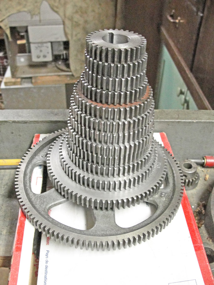
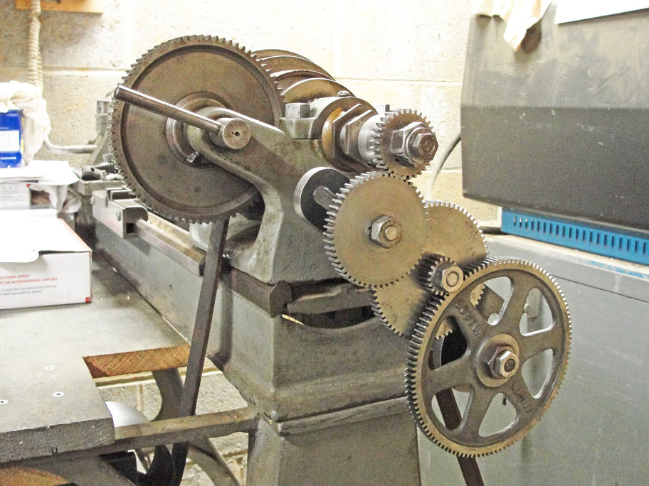
To make a long story short, I
made a set of change gears to replace the ones lost long ago (excepting
the bottom one, found in my junk drawer):
|
I had to make most of the blanks for the gears from scrap
metal; five of them came from a chunk of a link of anchor chin over
three inches in diameter that had been cut originally to make Charpy
impact test specimens:
|
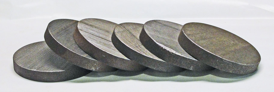
In order to save the last two of the five blanks, I had to
exactly bisect the last remnant of the chunk of anchor chain:
|
At last, after several slow days of hacksawing, I got the five blanks
with nothing at all left over:
|
Other noteworthy details:
Some of the newly purchased gear cutters for the DP20, 14-1/2 degree
pressure angle gears came from China with a metric bore that had to be
opened up with my fifty-year-old Dremel hand grinder:
|
Other blanks had to be
rounded out from pieces of rectangular plate, some by
drilling a series of nearly overlapping holes:

|
... others,
by putting the blank on an arbor and tolerating a tedious series of
interrupted cuts:
|
Here is the Sebastian
lathe's chart for threading with the original change gears:
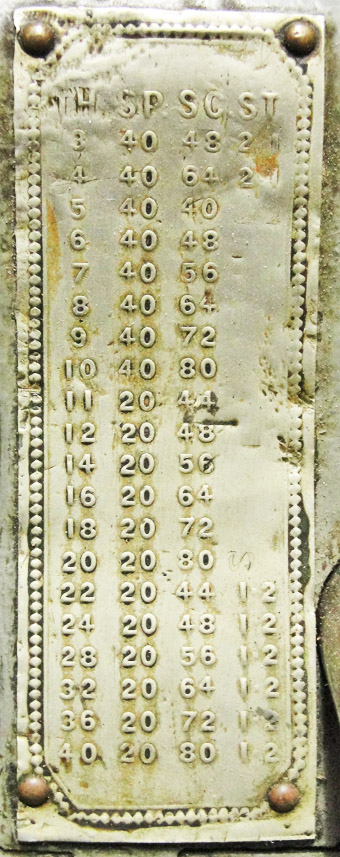
I also use a 40-tooth gear on the
spindle, but add a 30/60 cluster gear and an idler to get the necessary
even number of gears to produce right-handed screw threads and transfer
the motion from the spindle gear to the lead-screw gear. The lead screw
has left-handed threads.
My gears cover 5 to 80 threads per inch.
|
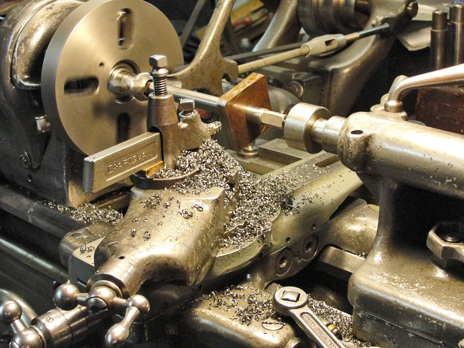
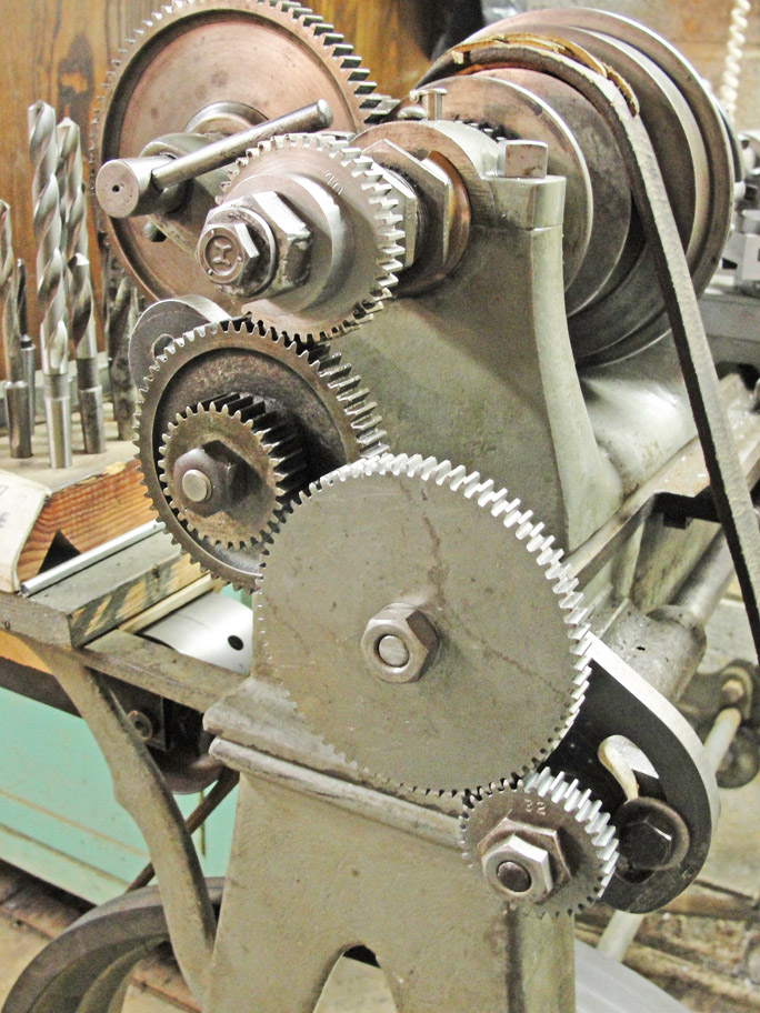
Examples of
some of the turning and threading gear trains:
Fine feed of 0.0042 inch per revolution of the spindle away
from the spindle:
|
Fine feed of 0.0056 inch per revolution of the spindle
towards the spindle:
|
Making an 8 tpi right-handed screw:
|
In order to fit these gears to the Sebastian lathe without
modifying anything on the lathe, I had to make a couple of important
adapters.
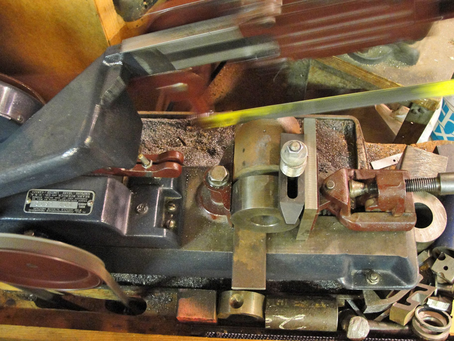
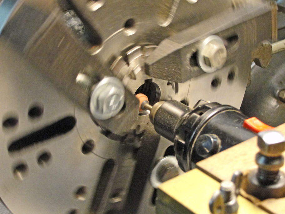
First,
there
had
to
be
means to hold the stud gear onto the main spindle:
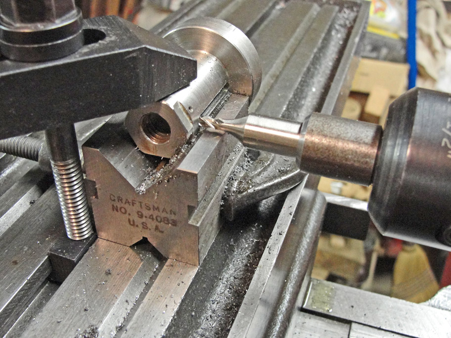
The stud gear
had to be driven by the left-hand end of the main spindle, so the
operation at left is the cutting of the keyway that keeps the stud gear
from rotating on the spindle; there's another key that keeps the
bushing from rotating.
|
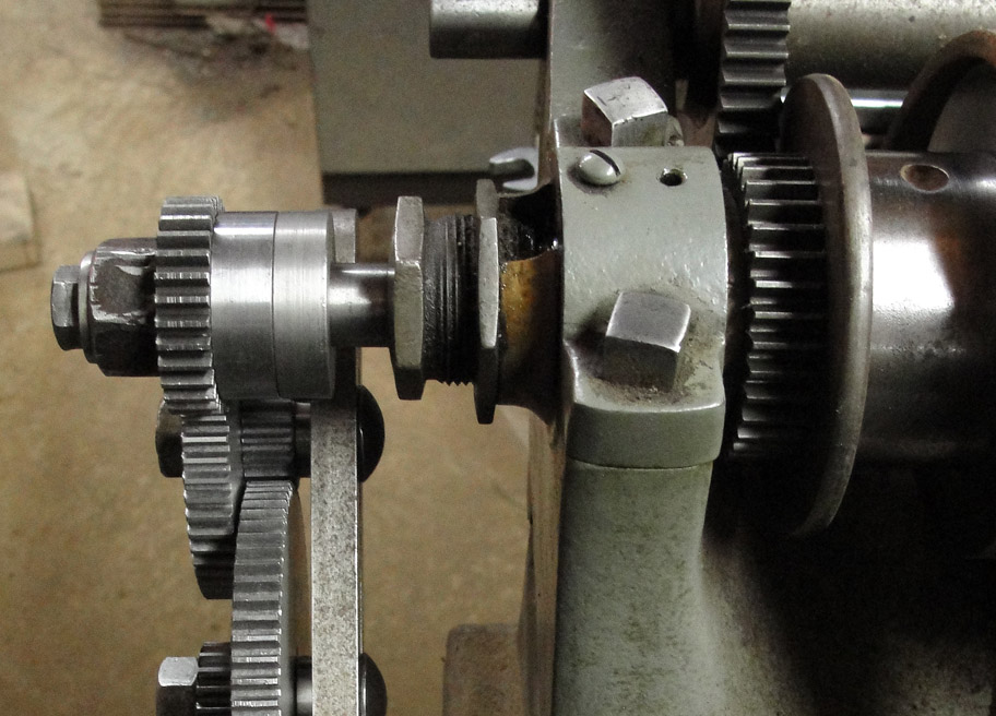
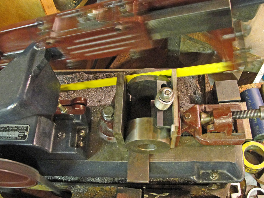
In the right-hand image the large nut is actually just a spacer, and
the small cap screw does the affixing of the stud gear. The
spacer between the stud gear and the bushing is used when the gear
train requires that the stud gear be on the outboard side as it is in
the image at left.
|
Second,
another adapter was needed to avoid modifying the lead screw:
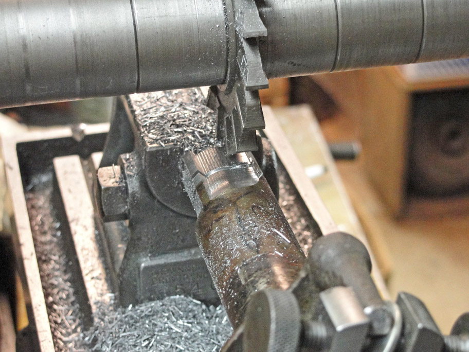
There was scant annular space between the inside diameter
of the
change gears and the outside diameter of the lead screw's means of
attaching the screw gear. There was just a short key in the lead
screw at its shoulder, and the gears all have longitudinal keyways like
standard change gears.
The first step was to rough out the integral key that fits
the change gear's keyway.
|
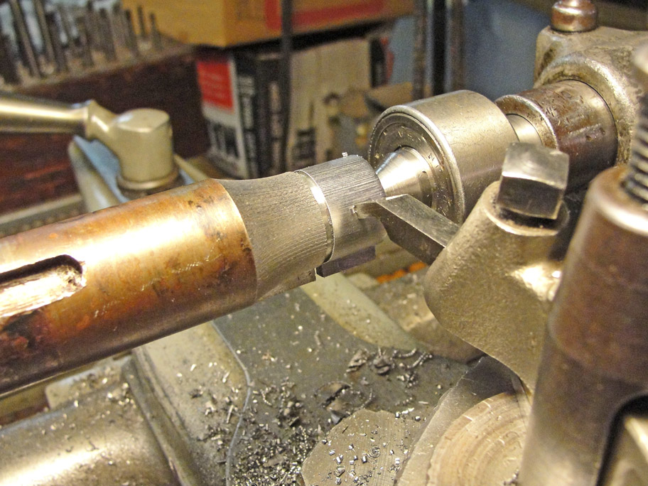
The second operation involved removing the ridges left by
the milling cutter, which I performed, somewhat tediously, by using the
handwheel feed of my lathe and a square-ended tool as a shaper.
After parting off the bushing, I bored it to fit the lead
screw of the Sebastian lathe and milled a short radial key to drive the
bushing, folowed by a great deal of hand filing and fitting to
accommodate all the change gears.
|
|