by George Langford
Apersands (&'s) removed from the URL's, September 15, 2005
Many of you could not view these images because of those non-ASCII characters in the addresses. Sorry; GL.
 |
In about
1975, I answered an advertisement in a local want-ad newspaper for a
planer for sale. It was being offered by a 95-year-old gentleman,
Mr.M.B. Gardner, who had made a career of making repair parts for
Linotype machines. He had modified this machine by lengthening
the table travel nearly three feet in order to work very long, thin
pieces. I have since reversed those changes. Mr. Gardner
had purchased the machine from Martin Machinery in Philadelphia, a firm
that was already familiar to me. He was giving up his shop
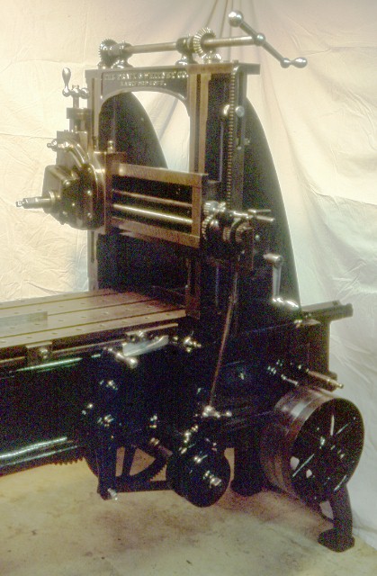
because of losing his eyesight to cataracts. We negotiated a price of $250 and I set about retrieving the machine. I rented a stake-bodied truck; by the time I arrived at his shop, Mr. Gardner had already taken down a wall of the shop, moved the planer out into the yard, and constructed a tripod. Actually, two tripods. The first wasn't sufficiently strong and failed dramatically. The second, made of doubled-up two by fours, three pairs of sixteen feet each, proved adequate. I got the machine home and off the truck with Mr. Gardner's tripod and a Harrington chain fall which he graciously lent me. Then I took the planer apart, down to the very last nut & bolt, in order to get it cleaned and moved into my basement, which has no outside entrance. Lots of rigging, wire brushing, paint scraping, and repainting later, the result appeared as at left. Getting it all back together was relatively easy, because the parts (nuts & bolts included) only go together one way. Each of the major parts was stamped with the numeral "8" as this was number 8 in its batch, and all the mating pairs had to be kept identified while various operations were performed. These original Kodachrome slides date to late 1977. The planer wasn't all together when I snapped this picture - there is now a countershaft mounted on wood blocks astride the uprights and a truck transmission and one-horse GE induction motor in the rear. I added an ammeter to watch the effects of heavy cuts on the power consumption. Most of the power goes into stopping and reversing the direction of table travel. |
 |
The belt shifting mechanism at left is not the same as that shown in the next image, taken from the 1900 Pratt & Whitney catalog, which depicts a shift mechanism patented by Dwight Slate, April 20, 1869 (US Patent No. 89,177) according to Kenneth L. Cope in his book, American Planer, Shaper and Slotter Builders. However, a tiny image in one of the books produced as an adjunct to 1876, the centennial of the1876 Philadelphia Centennial Exposition, where many of the original exhibits were retrieved and displayed at a stunning Smithsonian Institute exhibition in 1976, depicts my planer. At the end of the cutting stroke, the rocking lever strikes the stop at left. That causes the belt shifters to first move the driving belt onto its loose pulley and then the crossed reverse belt onto the drive pulley. The aluminum ramp at right makes for gentler belt shifts at the faster reverse speed. |
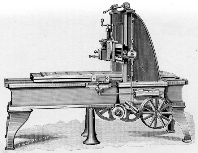 |
When you
compare the image at left, taken from my copy of the 1900 Pratt &
Whitney Descriptive Illustrated
Catalog, to the photograph of my planer at the top of this page,
you will see that the cross feed and belt shifting mechanisms are quite
different. My feeds not only move the saddle, but can
alternatively feed the compound downwards at any angle, thanks to some
bevel gears buried inside the saddle. There are a couple of
hand-filed gears in my planer's mechanism, definitely not originals. My planer needed a little attention to several things that had become worn or loosened, but the only major item was that I had to hand scrape the top of the cross rail in order to plane flat. Once that was done, I took about a ten mil cut across the entire length and breadth of the table to remove the dings and scratches and then applied a straightedge and dial indicator (ordinarily used to test surface plates) and found that the table was flat within 0.001 inch over the middle four feet (out of five) and the entire width. This is the smallest size, 16 by 16 inches, that P&W made. |