Making an internal hexagon on the South Bend 7" shaper
George Langford
June 28, 2006
| Working on a
project for which I needed repeatedly to recut external pipe threads
without any tendency to cock the rework die, I set about making an
internal hex socket to grip the hexagonal die without distortion.
The hex die is 2-3/8ths inch across the flats, and I wanted a good fit.
That meant working to thousandths of an inch, which eliminated simply
hacksawing and hand filing, which are usually quicker. The
workpiece was not going to fit easily in my little Atlas horizontal
milling machine, and I'd have had to use too small an end mill to match
the corner radii of the die. I have a vertical shaper attachment
for the Atlas MM, but it just won't stay in alignment without serious
attention to bracing, so I turned to my South Bend 7" shaper. The
workpiece could not be held in the shaper's vise while using the
internal keyway tool holder, so I had to take the vise off the knee of
the shaper. This was virtually a first for me, even after using
this shaper for forty-plus years. |
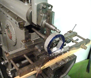 |
Here
is the setup. The workpiece is clamped against a 0.5 by 1.0 by
6.0 inch steel parallel. The parallel is in turn clamped to the
table by a 0.25 by 1.5 by 4.0 inch steel strap that has two,
5/16ths-18NC tapped holes, 2.0 inch apart that match the hole grid of
the shaper's table. A second 0.5 by 1.0 by 6.0 inch parallel holds up the rear edge of the strap. A
pair of toolmakers clamps secure the workpiece by clamping it with a
0.25 by 1.0 by 6.0 inch parallel resting on another 0.25 by 1.0 by 6.0
inch steel spacer. The wooden strip holds the toolmakers clamps
while I am emplacing the workpiece. The table has a shallow
V-groove in the middle that keeps the workpiece from rolling while I
fumble with the clamps. The clamping is rock steady, but if I had
accidentally run the tool holder into the back of the workpiece, the
clamps would have failed, saving the shaper's drive mechanism. I laid out the hexagon in classic plane-geometry fashion, using the property that the spacing of six corners on a circle of radius R is the same as that radius - one just uses dividers to step out the six locations by swinging the radius R from one mark to the next around the circle. It was quite satisfying to feel the divider hitting the first of the six pivot points on the sixth swing, proving that my layout was accurate. I then scribed lines between each pair of points around the circle to locate the six faces of the hexagon. I drilled a line of 3/16th inch holes inside the scribed lines, spaced to leave a minimum of metal between adjacent holes, and then I simply hammered out the waste. |
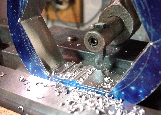 |
This was the sixth roughing cut. You can see the layout marks. I aligned each bottom-most line entirely by eye. I must be very good at this, because my inside-measuring dial calipers could not detect any lack of parallelism between opposing faces after the first round of six roughing cuts was complete. In the background is visible one of the two, 5/16-18NC studs securing the setup to the shaper's table by clamping the 0.5 by 1.0 by 6.0 inch rear parallels between the strap and the table. Cap screws would have worked just as well, but I would have had to trim their ends so as not to interfere with the tool holder at the extreme ends of each cutting traverse. |
 |
This
a dim view of the two clamping studs on the underside of the shaper
table. The nuts have spherical faces bearing against
spherical-surface washers; this is probably overkill, as there were no
parts not in parallel or perpendicular alignment in the setup. The brass crossfeed nut is just visible through the window at the rear of the table. |
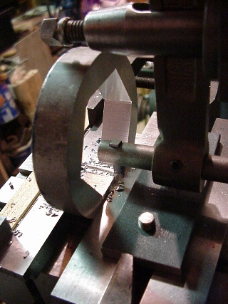 |
Spacings
between the shaper tool holder and other parts of the setup were
critical, as excessive clearances would have made the setup too
springy. The front of the tool holder had to come very close to
the back of the workpiece; it also had to miss the top of the clamping
strap at lower right; the tool post had to pass over the top of the
workpiece at upper left; and the rear end of the tool holder had to
pass through the window into the inside of the column of the
shaper. I got these right the first time, as the minimum
clearances during the final passes were on the order of 0.02
inch. I let the clapper box work freely, but I did have to adjust
its swing to provide clearance for each return stroke. The cutting tool has a horizontal bottom cutting edge, and each side edge has the usual clearance behind the cutting edge and also against the adjacent hex flat. The corners were left sharp, producing six sharp internal corners, even though the rework die has 3/32nd inch radii outer corners; overkill again. I was using a tool previously offhand ground for flycutting a large gear. I made one roughing cut on each face and then two finishing cuts. I hand filed the flats to pass the rework die without any tightness. At first, I pushed the die into and out of the hex socket with an arbor press and then simply draw filed the flats to remove the interference scrape markings. Lastly, I used a triangular file sharpened as a three cornered scraper to obtain a push fit. Then I made a symmetrical pair of 18-inch handles with 3/8ths inch steel bar stock and fastened them to the socket with a pair of 0.250 inch dowel pins pressed into letter drill G holes 180 degrees apart on the thickest portions of the socket. It takes about 150 foot-pounds to cut the 1-11-1/2 NPT threads in the solid brass plug that I am rethreading, but this gimbal mounting of the handles ensures that the heavy muscular effort doesn't cock the die. |
| Video Clip |
The
link at left leads to a 30-second MPEG video of the process, starting
from the front side of the setup and swinging around towards the right
to the same vantage point as in the still image immediately above. |