Author: George Langford, January 6, 2005
Joseph Nason of New York obtained US Patent No. 10,383 on January 3, 1854 for an "arrangement for cutting screws in lathes."
The patent drawings are reproduced below. Nason's patent covers
all the essentials: Master screw and the means for making an accurate
half nut; bar-mounted slide rest pivoting behind the lathe bed; use of
the master screw and half nut to traverse the tool holder across the
work so as to cut the thread; and change gears to cut any sub-multiple
of the pitch of the master screw.
Where did the manufacturers go from here ? I have not found any examples of the last three patents above, nor any other thread dial or mechanism to permit the use of one master screw to cut any number of thread pitches without being forced to keep the half nut engaged and reverse the spindle to bring the cutter back to the start of each cut. I have a B.C. Ames lathe with provision for a rear mounted thread chasing attachment much like the Pratt & Whitney lathe shown above, but none is present. Durkee's art seems to be the best starting place for making one, except that I would add a clapper (one-way pivot for pawl (34) to let me disengage the half nut (17) safely.
| Joseph Nason, US Patent No. 10,383 of January 3, 1854 |
 |
Joshua Rose described a lathe made by
G.H. Fox & Co. and their successor, American Tool & Machine of
Boston, Massachusetts in his ©1887 work, Modern Machine Shop Practice, published by Charles Scribners' Sons. That lathe, shown below in Rose's Figure 736, follows the Nason patent faithfully.
My 1900 Pratt & Whitney catalog carries their No.3 size model makers lathe, shown below in front and rear views.
So far, so good. Several lathe manufacturers made Fox lathes in this general pattern. They can be seen at the following fine website: http://www.lathes.co.uk/: Ames Cataract Goodell-Pratt Potter Stark Wade Waltham. However, every one of these lathes requires a change in the master screw if other pitches than the original multiples of the master screw are needed.
Three inventors tried to satisfy that need: Albert Latham in US Patent No. 631,576 (August 22, 1899); James L.L. McCormack in US Patent No. 1,497,109 (June 10, 1924); and Henry R. Durkee in US Patent No. 1,582,669 (April 27, 1926). Each inventor describes a means of permitting one master hob-screw to serve for all thread pitches. All the operator would have to do is select a suitable combination of change gears to obtain the desired thread pitch. Easier said than done ...
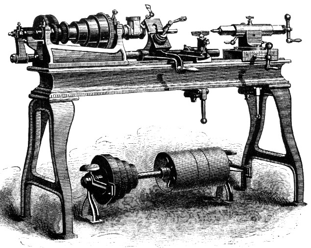 Quoting Rose's text that describes what was to become known as the Fox lathe: Quoting Rose's text that describes what was to become known as the Fox lathe:Fig. 73[6] represents a lathe designed and constructed by the American Tool and Machine Company, of Boston, Mass. This class of lathe is strictly of American origin, and has become the most important tool in the brass finishing shop. In its design the following advantages are obtained:-- 1st. The front of the lathe is entirely unobstructed by the ordinary lathe carriage and slide rest, hence the work may be more easily chucked and examined, while in the case of work requiring to be ground together, while one part is in the chuck, the trouble of moving the slide rest out of the way is entirely obviated. [mat'l referring to turret lathe skipped] 3rd. The rest for traversing single pointed cutting tools or chasers (for internal threads) is at the back of the lathe where it is out of the way. 4th. In place of the usual change wheels required to operate the lead screw, the chasing bar is operated by a single threaded collar or hob, which is more easy of application or removal. 5th. The slide rest carrying the screw cutting tool is capable of such adjustment, that the tool will thread successive pieces of duplicate work to an exactly equal diameter, so as to obviate the necessity of either measuring or trying the work after the tool has been accurately set for the first piece. 6th. When the threading tool has traversed to the end of its cut it may be lifted from the same and pulled back by hand, ready to take the second cut, thus avoiding the loss of time involved by traversing it back by a lead screw or its equivalent. [more material referring to the turret skipped] In the particular lathe shown in our example, there is another and special advantage as follows:-- In lathes operating upon small work and upon the softer metals, as composition, brass, etc., the time occupied in traversing the cutting tool is comparatively short, and from the comparative softness of the metal the speed of lathe rotation is quick, ... [more material referring just to the turret lathe skipped again] ... there is provided on the live spindle a ... small pinion, driving at the back of the lathe a shaft, on the left-hand end of which is a seat for collars or hobs, operating a bar running along the back of the lathe, and forming what is termed the screw apparatus, whose operation is as follows:-- This bar carries the slide rest shown, a handle or lever for partly rotating the slide rest, spanning the bed of the lathe. When this handle is lifted, the bar at the back of the lathe rotates in its journals. On this bar is an arm which carrieds a segment of a circle, containing a thread correspoding in pitch to the thread on the collar or hob. When the lever is raised the segment moves away from the hob, and the bar may be moved laterally by hand, but when the lever is lowered the arm falls, and the segment comes into contact with the hob thread, which therefore feeds the bar; all that is necessary for thread cuttingis, therefore, to place on the lathe a hob having the required pitch for the thread to be cut; and place in the slide rest a chaser or single-pointed threading tool, and set the tool to work by means of the slide rest, depressing the lever to cause the tool to feed forward, and elevating it to move the bar back by a lateral hand pressure. To put on successive cuts the slide rest is operated, the leaver always being lowered till it meets the surface of the lathe bed. To cause the slide rest to cut successive threads to the same diameter, a suitable stop motion is provided to the stop rest, and when the rest has been operated as far as the stop will permit it, the thread is cut to the required depth and diameter. |
My 1900 Pratt & Whitney catalog carries their No.3 size model makers lathe, shown below in front and rear views.
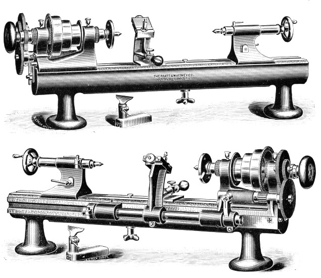 Quoting the P&W 1900 catalog: Quoting the P&W 1900 catalog:No.3 Thread Cutting Attachment
Is in many respects similar to the well known Fox Lathe Chasing Mechanism but presents several new and desirable features as will be seen in the front and rear views, showing attachment applied to the lathe in [the] [f]igure. There is furnished with the attachment one hob-screw or leader, the pitch of threads being left to the selection of the purchaser; it is made in one piece, one end of which is the hob for cutting the sectional nut used, the remaining portion constituting the lead screw. The gears sent with this attachment are accurately cut, great care being taken to make the subdivisions nearly as currect as is possible, commercially, and the set of gears furnished permit the cutting of any multiple of the hob-screw threads from 1 to 6, i.e., if the hob screw has 10 threads per inch, the threads which can be cut with these gears are 10, 290, 30, 40, 50 and 60. But one gear is attached to the spindle of the lathe, all the other gears being carried by an arm of the attachment. Means are provided for accurately adjusting the cutting tool to the center of the lathe; and it is not necessary with this attachment to use any reverse speed. The screw actuating the tool has a graduated nut reading to .001 in.; the action of the screw need not be reversed until the full depth of the cut has been made. Hob-screws of different number of threads per inch are kept in stock and are furnished to order independent of the attachment. Note that Pratt & Whitney's lathe has a spring-loaded half nut that permits the slide rest to be lowered a little at a time (controlled by the vertical-axis thumbscrew seen in both the front & rear vies above) so that the adjustment of the tool rest caould function mainly for fine adjustment of the cutting tool to compensate for wear. In that it differs from the original Nason patent (which provided a stop for the tool rest's feed) and the Fox lathe made by American Tool & Machine. |
So far, so good. Several lathe manufacturers made Fox lathes in this general pattern. They can be seen at the following fine website: http://www.lathes.co.uk/: Ames Cataract Goodell-Pratt Potter Stark Wade Waltham. However, every one of these lathes requires a change in the master screw if other pitches than the original multiples of the master screw are needed.
Three inventors tried to satisfy that need: Albert Latham in US Patent No. 631,576 (August 22, 1899); James L.L. McCormack in US Patent No. 1,497,109 (June 10, 1924); and Henry R. Durkee in US Patent No. 1,582,669 (April 27, 1926). Each inventor describes a means of permitting one master hob-screw to serve for all thread pitches. All the operator would have to do is select a suitable combination of change gears to obtain the desired thread pitch. Easier said than done ...
| Albert Latham, US Patent No. 631,576 of August 22, 1899 |
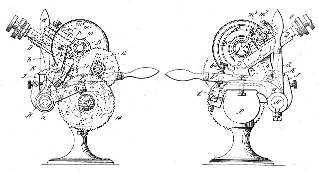 Albert
Latham provided a two-armed lever (K') actuated by cams on the master
screw (i) and on the spindle (h), which together moved a crank (g) to
lift a bar (K) that together with the pawl (J) otherwise would impede
the engagement of the half nut (F) with the master screw (E).
This arrangement required that the operator always bring the slide rest
back against a stop that set the starting point of the cutting
operation. Thoughtfully, there is a spring (27) to keep the
spindle's cam from striking its lever arm (22) at every single
rotation, which could be noisy as well as damaging to the cam.
Only the hob's cam struck the lever (23), but at a much lower
frequency, considering that the hob runs much slower than the spindle
so as to allow the hob's threads to becoarser and therefore more wear resistant. No patent assignment is known to this writer. Albert
Latham provided a two-armed lever (K') actuated by cams on the master
screw (i) and on the spindle (h), which together moved a crank (g) to
lift a bar (K) that together with the pawl (J) otherwise would impede
the engagement of the half nut (F) with the master screw (E).
This arrangement required that the operator always bring the slide rest
back against a stop that set the starting point of the cutting
operation. Thoughtfully, there is a spring (27) to keep the
spindle's cam from striking its lever arm (22) at every single
rotation, which could be noisy as well as damaging to the cam.
Only the hob's cam struck the lever (23), but at a much lower
frequency, considering that the hob runs much slower than the spindle
so as to allow the hob's threads to becoarser and therefore more wear resistant. No patent assignment is known to this writer. |
| James L.L. McCormack, US Patent No. 1,497,109 (June 10, 1924) |
 James
McCormack provides a double-dial threading indicator, wherein one dial
(58) is driven by gears (54 and 55) at the speed of the spindle (14)
and the second dial (61) is driven by gears (including two pairs of 1:2
miter gears not seen above) with the same ratio as gears (54 & 55)
at the speed of the master screw (16). Index marks are provided
on each dial; and each cut is commenced by the operator when those two
marks are seen again to be coming into coincidence as they did for the
first cut. In the patent drawings the dials are each driven (by
the aforementioned two, 1:2 miter gear pairs) at half the speed of
their respective spindles; provision is anticipated for smaller ratios
to facilitate threading at higher spindle speeds. In this
invention as well as in Latham's, the starting point for each cut must
be identical, that is, from a suitable stop. Patent assigned to
Hardinge Bros. Inc. of Chicago, Illinois.
|
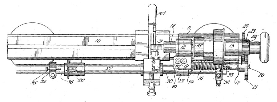
| Henry E. Durkee, US Patent No. 1,582,669 of April 27, 1926 |
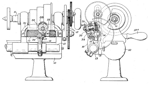 Henry
Durkee's master screw (14) drives a worm gear (20b) that has a suitably
large number of common factors with the pitch of the master screw
(forty-eight teeth in the patent example). A notched wheel (32)
is mounted on a common shaft (31) with the worm gear, the notches (33)
serving to allow engagement of the half nut (17) with the master screw
only when a suitable juxtaposition of master screw and hob is
reached. In the example shown in the patent drawings this happens
four times for each rotation of the worm gear. When the master
screw has a pitch of ten per inch, the four notches in the wheel
correspond to twelve rotations of the hob. If the desired
workpiece thread pitch is 32 and the master screw is geared (15) to
rotate at 10/32 the speed of the spindle, a notch coincides with the
pawl (34) on the half nut once every 36.4 rotations of the
workpiece. A fixed stop for the rear slide is unnecessary.
Note that the operator must wait until a notch and the pawl again come
into correct position in order to retract the tool. Patent
assigned to Pratt & Whitney Co. of New York. Henry
Durkee's master screw (14) drives a worm gear (20b) that has a suitably
large number of common factors with the pitch of the master screw
(forty-eight teeth in the patent example). A notched wheel (32)
is mounted on a common shaft (31) with the worm gear, the notches (33)
serving to allow engagement of the half nut (17) with the master screw
only when a suitable juxtaposition of master screw and hob is
reached. In the example shown in the patent drawings this happens
four times for each rotation of the worm gear. When the master
screw has a pitch of ten per inch, the four notches in the wheel
correspond to twelve rotations of the hob. If the desired
workpiece thread pitch is 32 and the master screw is geared (15) to
rotate at 10/32 the speed of the spindle, a notch coincides with the
pawl (34) on the half nut once every 36.4 rotations of the
workpiece. A fixed stop for the rear slide is unnecessary.
Note that the operator must wait until a notch and the pawl again come
into correct position in order to retract the tool. Patent
assigned to Pratt & Whitney Co. of New York. |
Where did the manufacturers go from here ? I have not found any examples of the last three patents above, nor any other thread dial or mechanism to permit the use of one master screw to cut any number of thread pitches without being forced to keep the half nut engaged and reverse the spindle to bring the cutter back to the start of each cut. I have a B.C. Ames lathe with provision for a rear mounted thread chasing attachment much like the Pratt & Whitney lathe shown above, but none is present. Durkee's art seems to be the best starting place for making one, except that I would add a clapper (one-way pivot for pawl (34) to let me disengage the half nut (17) safely.