Method 1 -
January
21, 2005
 The Atlas
Press Co. 10 inch lathe that I purchased for my son had a form of
metallurgical cancer in the Zamak aluminum-zinc alloy gears.
Several teeth fell right out of the main bull gear on the headstock,
and closer examination revealed swelling and cracks everywhere on the
gear. So I had to machine a new one to make the lathe
functional. Even though Atlas's owner, Clausing, is extremely
cooperative and
helpful, a new wrought aluminum gear from them was way outside my
budget.
The Atlas
Press Co. 10 inch lathe that I purchased for my son had a form of
metallurgical cancer in the Zamak aluminum-zinc alloy gears.
Several teeth fell right out of the main bull gear on the headstock,
and closer examination revealed swelling and cracks everywhere on the
gear. So I had to machine a new one to make the lathe
functional. Even though Atlas's owner, Clausing, is extremely
cooperative and
helpful, a new wrought aluminum gear from them was way outside my
budget.
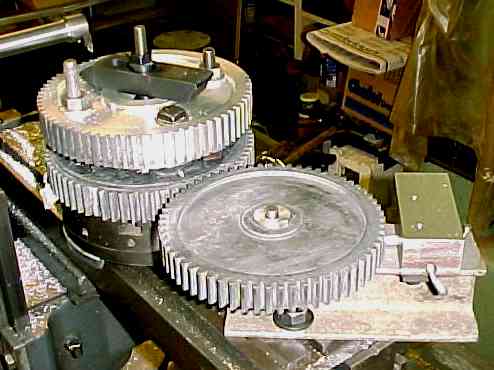
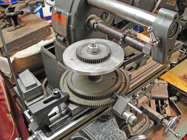
Problem
was, the gear was so large that I could not swing it on the
Atlas index head and still get a gear cutter over the top. So the
gear had to be machined horizontally on the Atlas's meager rotary
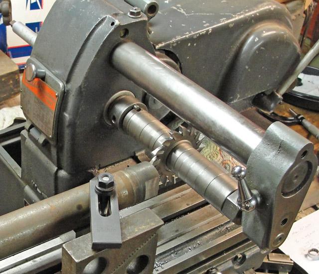
table, which has no indexing capability whatsoever. My solution
is shown at left. The bad gear is mounted flat on the rotary
table. Above it is the new gear, with about three-quarters of its
teeth already cut. In the foreground is the Atlas lathe's second
back gear, removed from the gear cluster for the time being. The
index pawl is at the far right. The pawl engages the teeth of the
intact second back gear, and that gear's teeth average out the errors
and bridge over the gaps in the defunct bull gear. The gear was about
three-quarters finished when I took the picture. |
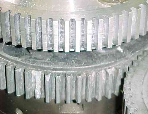 The new gear
teeth are shown above the bad bull gear's teeth at left. I
offhand ground the fly cutter, so these are not the quietest teeth on
the planet. But they work great. After a little running in,
the meshing quieted down. I did take a lot of trouble to make the
fit of the bore of the gear blank very close to the seat on the outside
of the spindle and to mount the blank concentrically on the rotary
table, and that worked out well.
The new gear
teeth are shown above the bad bull gear's teeth at left. I
offhand ground the fly cutter, so these are not the quietest teeth on
the planet. But they work great. After a little running in,
the meshing quieted down. I did take a lot of trouble to make the
fit of the bore of the gear blank very close to the seat on the outside
of the spindle and to mount the blank concentrically on the rotary
table, and that worked out well.
The idler gear rotates on a shaft mounted on the I-beam; I left it free
to rotate, held only by the index pawl. Of course, once I had
indexed to each new tooth, I took up the slack and then tightened the
clamps that kept the rotary table and the gears bolted to it from
rotating. So everything was nice and tight when I started each
cut. There's lots of impacting from that fly cutter, seen at top
left of the image at left. Note
that I fed the knee upwards to get a smooth motion without the force of
the cutter tending to lift the
knee or saddle.
The principal limitation of this technique is the reach of the fly
cutter. It would be more rigid to use the Atlas's overarm to
support the outboard end of the flycutter. One might make a gear
a foot across; I haven't checked what the exact limit might be. |
|
Method
2 - June 13, 2013
 Method 1 was necessitated by that cancerous
bull gear. The present Method 2 came out of my decision to complete the
set of metric change gears that I started about 25 years ago. I started
with the composite 127/100 gear set from South Bend lathe that can be
seen at
the bottom of the stack in the image at left. The large aluminum plate
near the top of the stack is the intended lead screw gear, which is to
be a
copy of the 100-tooth gear in the 127/100 composite, but with a 0.5625
(i.e., 9/16) inch bore and 0.125 (i.e., 1/8) inch keyway. You may also
notice that I've graduated to a real gearcutter, which in turn
necessitated making the 0.875 (i.e., 7/8) inch arbor seen at left.
Method 1 was necessitated by that cancerous
bull gear. The present Method 2 came out of my decision to complete the
set of metric change gears that I started about 25 years ago. I started
with the composite 127/100 gear set from South Bend lathe that can be
seen at
the bottom of the stack in the image at left. The large aluminum plate
near the top of the stack is the intended lead screw gear, which is to
be a
copy of the 100-tooth gear in the 127/100 composite, but with a 0.5625
(i.e., 9/16) inch bore and 0.125 (i.e., 1/8) inch keyway. You may also
notice that I've graduated to a real gearcutter, which in turn
necessitated making the 0.875 (i.e., 7/8) inch arbor seen at left.
|
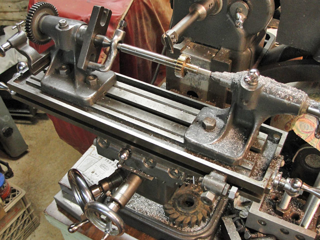 Another task
was making the four smaller gears (18, 20, 22 & 26 teeth) that are
also needed to cover the
expected range of metric thread pitches. I made the first of these with
the same flycutter (albeit ground to match the smaller gears in the
lathe's normal English change gears, which of course are all
interchangeable with the same 18 diametral pitch, 14-1/2 degree
pressure angle as the metric change gears). Shown at left is the Atlas
indexing head and the master gear (twice as many teeth, hence skipping
every other tooth with the index pin). The others I made with
gearcutters.
Another task
was making the four smaller gears (18, 20, 22 & 26 teeth) that are
also needed to cover the
expected range of metric thread pitches. I made the first of these with
the same flycutter (albeit ground to match the smaller gears in the
lathe's normal English change gears, which of course are all
interchangeable with the same 18 diametral pitch, 14-1/2 degree
pressure angle as the metric change gears). Shown at left is the Atlas
indexing head and the master gear (twice as many teeth, hence skipping
every other tooth with the index pin). The others I made with
gearcutters.
|
|
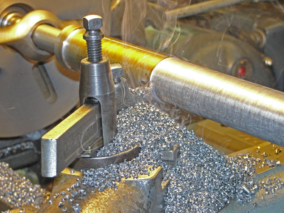
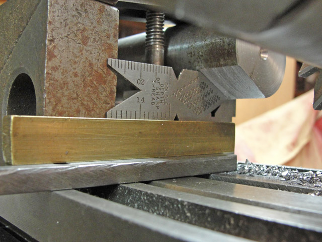
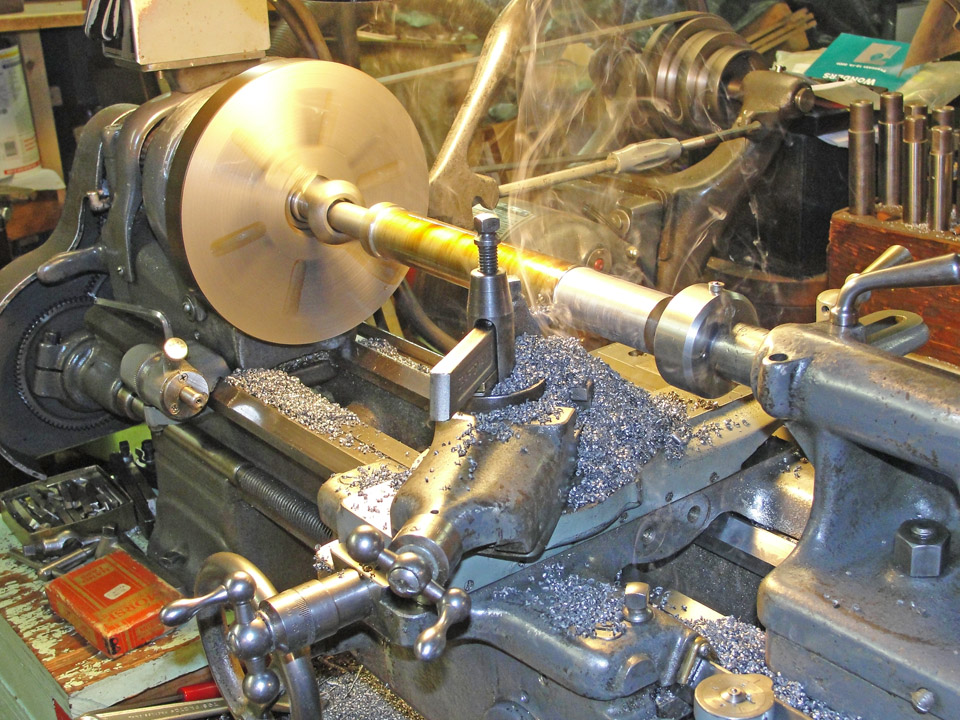 To make the 7/8 inch arbor, I hunted around my basement and found a
likely looking piece of ferrous material, but on the first pass it
became clear that I was machining a piece
of
wrought iron. Except for needing to sharpen the high speed steel
cutting tool frequently, it was easy to work accurately; note the pile
of short, curly chips. Not shown is the splinter of slag that I got
while caressing my fine work ...
To make the 7/8 inch arbor, I hunted around my basement and found a
likely looking piece of ferrous material, but on the first pass it
became clear that I was machining a piece
of
wrought iron. Except for needing to sharpen the high speed steel
cutting tool frequently, it was easy to work accurately; note the pile
of short, curly chips. Not shown is the splinter of slag that I got
while caressing my fine work ...
The images at right show the chip pile in greater detail
as well as my process for making the 5/8 inch clamping nut for the
arbor.
|
|
|
|
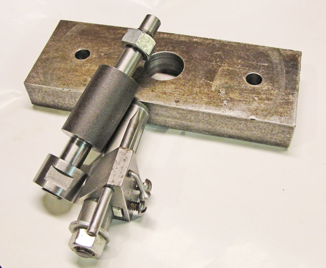
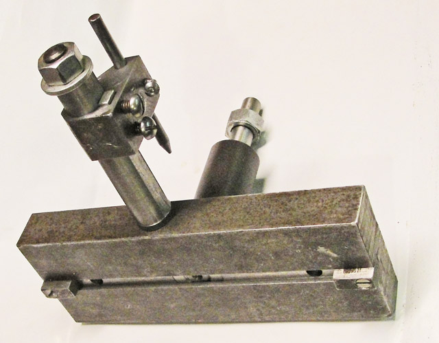
The series of images
below show the completed vertical arbor, which consists of two main
pieces: A base, made from a piece of 1x3x8 inch cold rolled steel,
which only needed a receptacle bored out to a close fit to the lower
clamping nut of the gear carrier, a keyway to fit the Atlas main table,
holes for the clamping screws and tee nuts that hold the base down, and
an adjustable index pin to accommodate the master gear. The adjustable
index pin is held by a sliding member that is keyed to the tubular
support arm. When I cut the present 100-tooth gear, I moved one
of the spacer gears underneath the blank, the better to support it
against the downward force exerted by the gear cutter. Making
non-cluster gears will necessitate making a new gear carrier to fit the
9/16 inch bore of separate change gears.
 Here's the setup, shown towards the end of
the three-hour tooth-forming process. The two strap clamps are keeping
the gear carrier and master gear from rotating and take the load off
the index pin. There was some vibration of the gear carrier because of
deflection of the 100-tooth master gear (second from the bottom) whose
web is rather thin. Next time I will wedge spacers between the two
gears or separate them entirely and use a flat-plate spacer on top of
the master gear. The cutter passed through the first tooth gap cleanly
after the gear was finished, proving that nothing had slipped. Here's the setup, shown towards the end of
the three-hour tooth-forming process. The two strap clamps are keeping
the gear carrier and master gear from rotating and take the load off
the index pin. There was some vibration of the gear carrier because of
deflection of the 100-tooth master gear (second from the bottom) whose
web is rather thin. Next time I will wedge spacers between the two
gears or separate them entirely and use a flat-plate spacer on top of
the master gear. The cutter passed through the first tooth gap cleanly
after the gear was finished, proving that nothing had slipped.
In practice the 127 tooth member of the 127/100 compound
gear is driven by the lathe's stud gear (which rotates at the same rate
as the lathe spindle), and the 100 tooth member of the 127/100 compound
gear in turn drives the 0.125 inch pitch lead screw, either through a
72 tooth idler for the 6.00 mm through 2.00 mm thread pitches, directly
for the 1.75 mm through 0.40 mm pitches, or with a 4:1 reduction by the
72/18 tooth compound gear that is part of the standard English thread
change gear set. The 100 tooth change gear that I just made is used
alternately with the 80 tooth change gear from the English thread
change gear set on the English lead screw.
I did not make a proper metric change gear setup for the
image at right, which was intended simply to demonstrate to myself that
the 100 tooth gear meshes correctly with the other 18 DP, 14-1/2 PA
gears without excessive runout. OK !!
|

|
Note: Most of the above images can be
viewed in greater detail by right-clicking with the mouse and selecting
"view image."
|